The Mcp2515 Obd2 interface provides a pathway to accessing and interpreting vehicle data. Discover how to effectively use this tool for accurate automotive diagnostics with guidance from OBD2-SCANNER.EDU.VN.
Contents
- 1. What is the MCP2515 OBD2 Interface?
- 1.1 Key Features of the MCP2515
- 1.2 MCP2515 and OBD2 Standards
- 2. Essential Components for MCP2515 OBD2 Integration
- 2.1 Microcontroller
- 2.2 CAN Transceiver
- 2.3 OBD2 Connector
- 2.4 Level Shifters (If Needed)
- 2.5 Power Supply
- 2.6 Additional Passive Components
- 2.7 Prototype Board or PCB
- 2.8 Wiring and Connectors
- 3. Setting Up the MCP2515 with Arduino
- 3.1 Hardware Connection
- 3.2 Software Setup
- 3.3 Code Example
- 4. Sending OBD2 Requests with MCP2515
- 4.1 Understanding OBD2 PIDs
- 4.2 Constructing a CAN Message
- 4.3 Code Example for Sending a Request
- 4.4 Receiving and Interpreting Responses
- 4.5 Interpreting Engine RPM Data
- 4.6 Complete Code Example
- 5. Common Issues and Troubleshooting
- 5.1 Initialization Problems
- 5.2 No CAN Messages Received
- 5.3 Incorrect Data
- 5.4 CAN Bus Errors
- 5.5 Software and Library Issues
- 5.6 Vehicle Compatibility
- 5.7 Power Supply Issues
- 6. Advanced Applications of MCP2515 OBD2
- 6.1 Custom Dashboards and Data Logging
- 6.2 Vehicle Security Systems
- 6.3 Automotive Research and Development
- 6.4 CAN Bus Reverse Engineering
- 6.5 Integration with IoT Platforms
- 7. Understanding CAN Bus Protocol
- 7.1 Key Concepts
- 7.2 CAN Message Structure
- 7.3 CAN Bus Arbitration
- 7.4 CAN Bus Error Handling
- 7.5 CAN Bus Standards
- 8. Optimizing MCP2515 OBD2 Performance
- 8.1 Hardware Considerations
- 8.2 Software Optimizations
- 8.3 CAN Bus Optimization
- 8.4 Example Scenario: Optimizing Data Logging
- 9. Understanding OBD2 Error Codes (DTCs)
- 9.1 DTC Structure
- 9.2 Common DTC Categories
- 9.3 Examples of Common DTCs
- 9.4 Reading and Clearing DTCs
- 9.5 Interpreting DTCs
- 10. Safety Precautions When Working with OBD2
- 10.1 General Safety Guidelines
- 10.2 Electrical Safety
- 10.3 Vehicle Safety
- 10.4 Data Security
- FAQ: MCP2515 and OBD2
- What is an OBD2 scanner?
- How do I read OBD2 error codes?
- What are common car problems and how can OBD2 help?
- Can I use an OBD2 scanner to improve fuel efficiency?
- What is the role of the MCP2515 in OBD2 diagnostics?
- Is it possible to build my own OBD2 scanner using MCP2515?
- What are the limitations of using MCP2515 for OBD2 diagnostics?
- How can OBD2-SCANNER.EDU.VN help with my OBD2 projects?
- What are the benefits of using OBD2 data for vehicle maintenance?
- What future trends can we expect in OBD2 technology?
- Conclusion: Mastering MCP2515 OBD2 for Automotive Excellence
1. What is the MCP2515 OBD2 Interface?
The MCP2515 is a standalone CAN (Controller Area Network) controller with an SPI interface, crucial for OBD2 diagnostics. According to Bosch, the inventor of CAN, this protocol allows microcontrollers and devices to communicate with each other within a vehicle without a host computer. It acts as a bridge, enabling microcontrollers to access and interpret data transmitted through a vehicle’s OBD2 port. This is essential for tasks such as reading diagnostic trouble codes (DTCs), monitoring engine performance, and customizing vehicle settings.
1.1 Key Features of the MCP2515
- CAN Protocol Support: Implements CAN protocol versions 2.0A and 2.0B.
- SPI Interface: Facilitates easy communication with microcontrollers.
- Message Filtering: Allows filtering of irrelevant messages, reducing processing overhead.
- Multiple Operating Modes: Offers various modes, including Listen Only, Loopback, and Normal operation.
- Low Power Consumption: Suitable for automotive applications.
1.2 MCP2515 and OBD2 Standards
The MCP2515’s ability to interface with the CAN bus makes it essential for OBD2 (On-Board Diagnostics II) applications. The OBD2 standard mandates that all vehicles sold in the US after 1996 have a standardized diagnostic port. This port allows technicians and enthusiasts to access a wealth of information about the vehicle’s health and performance.
2. Essential Components for MCP2515 OBD2 Integration
To effectively integrate the MCP2515 into an OBD2 system, you’ll need several key components.
2.1 Microcontroller
- Role: Serves as the central processing unit, interpreting data from the MCP2515 and executing diagnostic commands.
- Popular Options: Arduino, ESP32, STM32.
2.2 CAN Transceiver
- Role: Acts as an intermediary between the MCP2515 and the vehicle’s CAN bus, converting signals for proper communication.
- Common Choices: TJA1050, MCP2551.
2.3 OBD2 Connector
- Role: Provides the physical connection to the vehicle’s OBD2 port, allowing data transfer between the diagnostic tool and the car’s computer.
- Standard Type: SAE J1962.
2.4 Level Shifters (If Needed)
- Role: Adjusts voltage levels to ensure compatibility between components, preventing damage from voltage mismatches.
- Typical Use: When interfacing 3.3V microcontrollers with 5V CAN transceivers.
2.5 Power Supply
- Role: Provides a stable power source for all electronic components, ensuring consistent and reliable operation.
- Requirements: Typically 3.3V or 5V, depending on the components used.
2.6 Additional Passive Components
- Resistors, Capacitors, and Crystals: Essential for signal conditioning, filtering, and timing. Their values should be chosen based on the specific requirements of the circuit and components.
2.7 Prototype Board or PCB
- Role: Provides a platform for assembling and testing the circuit, allowing for easy connection and modification of components.
- Options: Breadboard for prototyping, custom PCB for a more permanent solution.
2.8 Wiring and Connectors
- Role: Establishes reliable connections between all components, ensuring proper signal and power distribution.
- Requirements: High-quality wires and connectors to minimize signal loss and ensure durability.
 Components for MCP2515 OBD2 Integration
Alt: Image showing components for integrating MCP2515 with OBD2, including Arduino microcontroller, CAN transceiver TJA1050, OBD2 connector, and various electronic components like resistors and capacitors on a breadboard.
3. Setting Up the MCP2515 with Arduino
Interfacing the MCP2515 with an Arduino board is a common and effective way to start working with OBD2 data. Here’s a step-by-step guide:
3.1 Hardware Connection
- Connect MCP2515 to Arduino: Connect the SPI pins (SCK, MISO, MOSI) and CS pin of the MCP2515 to the corresponding pins on the Arduino. Also, connect the INT pin to a digital pin on the Arduino for interrupt handling.
- Connect CAN Transceiver: Connect the MCP2551 or TJA1050 CAN transceiver to the MCP2515. The TX and RX pins of the MCP2515 should be connected to the corresponding pins on the transceiver.
- Connect OBD2 Connector: Connect the CAN High (CANH) and CAN Low (CANL) wires from the CAN transceiver to the corresponding pins on the OBD2 connector.
3.2 Software Setup
-
Install CAN Library: Use the Arduino Library Manager to install an appropriate CAN library, such as “mcp_can.”
-
Include Library: Include the library in your Arduino sketch:
#include <mcp_can.h> #include <SPI.h> -
Define Pins: Define the necessary pins for the CAN controller:
#define CAN0_INT 2 // Interrupt pin MCP_CAN CAN0(10); // CS pin -
Initialize CAN: Initialize the CAN controller in the
setup()function:void setup() { Serial.begin(115200); if (CAN0.begin(MCP_STDEXT, CAN_500KBPS, MCP_8MHZ) == CAN_OK) { Serial.println("MCP2515 Initialized Successfully!"); } else { Serial.println("Error Initializing MCP2515..."); while (1); } CAN0.setMode(MCP_NORMAL); pinMode(CAN0_INT, INPUT); }
3.3 Code Example
Here’s a simple Arduino sketch to read and display CAN messages:
#include <mcp_can.h>
#include <SPI.h>
#define CAN0_INT 2
MCP_CAN CAN0(10);
void setup() {
  Serial.begin(115200);
  if (CAN0.begin(MCP_STDEXT, CAN_500KBPS, MCP_8MHZ) == CAN_OK) {
    Serial.println("MCP2515 Initialized Successfully!");
  } else {
    Serial.println("Error Initializing MCP2515...");
    while (1);
  }
  CAN0.setMode(MCP_NORMAL);
  pinMode(CAN0_INT, INPUT);
}
void loop() {
if (!digitalRead(CAN0_INT)) {
unsigned long rxId;
byte dlc;
byte rxBuf[8];
CAN0.readMsgBuf(&rxId, &dlc, rxBuf);
Serial.print("ID: 0x");
Serial.print(rxId, HEX);
Serial.print(" DLC: ");
Serial.print(dlc);
Serial.print(" Data: ");
for (int i = 0; i < dlc; i++) {
Serial.print(rxBuf[i], HEX);
Serial.print(" ");
}
Serial.println();
}
}This code initializes the MCP2515, sets up the interrupt pin, and reads incoming CAN messages, printing them to the serial monitor.
4. Sending OBD2 Requests with MCP2515
Sending OBD2 requests involves crafting specific CAN messages and transmitting them through the MCP2515 interface. This allows you to query the vehicle’s ECU (Engine Control Unit) for diagnostic information.
4.1 Understanding OBD2 PIDs
OBD2 PIDs (Parameter IDs) are codes used to request specific data from the vehicle’s ECU. Each PID corresponds to a particular sensor or parameter, such as engine speed, coolant temperature, or fuel level.
- Example: PID
0x0Crequests engine RPM (Revolutions Per Minute).
4.2 Constructing a CAN Message
To send an OBD2 request, you need to construct a CAN message with the appropriate ID and data.
- CAN ID: The CAN ID typically used for OBD2 requests is
0x7E0for the ECU and0x7E8for responses. These IDs may vary based on the vehicle’s protocol. - Data Bytes: The data bytes contain the OBD2 service and PID.
- Byte 1: Number of data bytes following (usually
0x02for a standard request). - Byte 2: OBD2 service (e.g.,
0x01for current data requests). - Byte 3: PID to request (e.g.,
0x0Cfor engine RPM). - Bytes 4-8: Padding bytes (usually
0x00or0x55).
- Byte 1: Number of data bytes following (usually
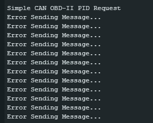
4.3 Code Example for Sending a Request
Here’s an example of sending a request for engine RPM (PID 0x0C):
#include <mcp_can.h>
#include <SPI.h>

#define CAN0_INT 2
MCP_CAN CAN0(10);

void setup() {
  Serial.begin(115200);
  if (CAN0.begin(MCP_STDEXT, CAN_500KBPS, MCP_8MHZ) == CAN_OK) {
    Serial.println("MCP2515 Initialized Successfully!");
  } else {
    Serial.println("Error Initializing MCP2515...");
    while (1);
  }
  CAN0.setMode(MCP_NORMAL);
  pinMode(CAN0_INT, INPUT);
}

void loop() {
  byte data[8] = {0x02, 0x01, 0x0C, 0x55, 0x55, 0x55, 0x55, 0x55};
  CAN0.sendMsgBuf(0x7E0, 8, data);
  delay(100);
}
This code sends a CAN message with ID 0x7E0 and the specified data to request engine RPM.
4.4 Receiving and Interpreting Responses
After sending a request, the ECU will respond with a CAN message containing the requested data.
- Check CAN ID: Ensure the response is from the expected CAN ID (usually
0x7E8). - Extract Data: The response data will vary depending on the PID. Typically, the first byte indicates the number of data bytes, the second byte is
0x41(response to service0x01), and the following bytes contain the actual data.
4.5 Interpreting Engine RPM Data
For engine RPM (PID 0x0C), the data is usually two bytes. The RPM is calculated as:
RPM = ((A * 256) + B) / 4
Where A and B are the two data bytes.
4.6 Complete Code Example
Here’s a complete example that sends an engine RPM request and interprets the response:
#include <mcp_can.h>
#include <SPI.h>

#define CAN0_INT 2
MCP_CAN CAN0(10);

void setup() {
  Serial.begin(115200);
  if (CAN0.begin(MCP_STDEXT, CAN_500KBPS, MCP_8MHZ) == CAN_OK) {
    Serial.println("MCP2515 Initialized Successfully!");
  } else {
    Serial.println("Error Initializing MCP2515...");
    while (1);
  }
  CAN0.setMode(MCP_NORMAL);
  pinMode(CAN0_INT, INPUT);
}

void loop() {
  byte sendData[8] = {0x02, 0x01, 0x0C, 0x55, 0x55, 0x55, 0x55, 0x55};
  CAN0.sendMsgBuf(0x7E0, 8, sendData);
  delay(50);

  if (!digitalRead(CAN0_INT)) {
    unsigned long rxId;
    byte dlc;
    byte rxBuf[8];
    CAN0.readMsgBuf(&rxId, &dlc, rxBuf);

    if (rxId == 0x7E8) {
      int a = rxBuf[3];
      int b = rxBuf[4];
      float rpm = ((a * 256) + b) / 4;
      Serial.print("Engine RPM: ");
      Serial.println(rpm);
    }
  }
  delay(950);
}
5. Common Issues and Troubleshooting
Working with the MCP2515 and OBD2 can present several challenges. Here’s a guide to some common issues and how to troubleshoot them.
5.1 Initialization Problems
- Issue: MCP2515 fails to initialize.
- Possible Causes: Incorrect wiring, incorrect clock frequency, or faulty MCP2515 chip.
- Troubleshooting Steps:
- Verify Wiring: Double-check all connections between the Arduino and MCP2515.
- Check Clock Frequency: Ensure the clock frequency in your code matches the actual crystal frequency (e.g., 8MHz or 16MHz).
- Test Chip: Try using a different MCP2515 chip to rule out a faulty component.
- Use a Multimeter: Verify the power supply to the MCP2515 is stable and within the specified voltage range.
5.2 No CAN Messages Received
- Issue: The Arduino is not receiving any CAN messages.
- Possible Causes: Incorrect CAN bus speed, filtering issues, or problems with the CAN transceiver.
- Troubleshooting Steps:
- Check CAN Bus Speed: Ensure the CAN bus speed in your code (e.g., 500kbps) matches the vehicle’s CAN bus speed.
- Disable Filters: Temporarily disable all filters to see if any messages are received. If messages appear, adjust the filters correctly.
- Verify Transceiver: Check the connections to the CAN transceiver (TJA1050 or MCP2551) and ensure it is properly powered.
5.3 Incorrect Data
- Issue: The received data is incorrect or nonsensical.
- Possible Causes: Incorrect PID, incorrect data interpretation, or endianness issues.
- Troubleshooting Steps:
- Verify PID: Double-check the PID you are requesting.
- Check Data Interpretation: Ensure you are correctly interpreting the received data according to the OBD2 standard and the vehicle’s specific protocol.
- Handle Endianness: Be aware of endianness (byte order) issues, especially when dealing with multi-byte data.
5.4 CAN Bus Errors
- Issue: Frequent CAN bus errors or communication failures.
- Possible Causes: Wiring issues, termination problems, or bus contention.
- Troubleshooting Steps:
- Check Wiring: Ensure the CAN High (CANH) and CAN Low (CANL) wires are correctly connected and not shorted.
- Verify Termination: Ensure the CAN bus is properly terminated with 120-ohm resistors at each end of the bus.
- Reduce Bus Load: If multiple devices are on the CAN bus, try reducing the number of devices to minimize bus contention.
5.5 Software and Library Issues
- Issue: Problems with the Arduino code or CAN library.
- Possible Causes: Library conflicts, outdated library versions, or errors in the code.
- Troubleshooting Steps:
- Update Libraries: Ensure you are using the latest version of the CAN library.
- Check Code for Errors: Review your code for any syntax errors, logical errors, or incorrect function calls.
- Simplify Code: Try simplifying your code to isolate the source of the problem.
- Consult Documentation: Refer to the CAN library documentation for troubleshooting tips and example code.
5.6 Vehicle Compatibility
- Issue: The OBD2 adapter does not work with a specific vehicle.
- Possible Causes: Protocol incompatibility, incorrect PID support, or issues with the vehicle’s ECU.
- Troubleshooting Steps:
- Check Protocol: Verify that the OBD2 adapter supports the vehicle’s protocol (e.g., CAN, ISO 9141-2, SAE J1850 PWM/VPW).
- Verify PID Support: Ensure that the vehicle’s ECU supports the PIDs you are requesting.
- Try Another Vehicle: Test the OBD2 adapter with another vehicle to rule out issues with the adapter itself.
5.7 Power Supply Issues
- Issue: The electronic components are not functioning correctly.
- Possible Causes: Insufficient or unstable power supply.
- Troubleshooting Steps:
- Check Voltage Levels: Use a multimeter to ensure that the voltage levels are within the specified range for each component.
- Verify Stability: Ensure that the power supply is stable and free from voltage fluctuations.
- Use Separate Power Supplies: If possible, use separate power supplies for the Arduino and MCP2515 to isolate any potential issues.
6. Advanced Applications of MCP2515 OBD2
Beyond basic diagnostics, the MCP2515 OBD2 interface can be used in advanced applications for automotive enthusiasts and professionals.
6.1 Custom Dashboards and Data Logging
- Create Custom Dashboards: Display real-time vehicle data on custom dashboards using LCD screens or smartphone apps.
- Data Logging: Log vehicle data over time for performance analysis and diagnostics.
- Applications: Performance tuning, fuel efficiency monitoring, and driver behavior analysis.
6.2 Vehicle Security Systems
- Implement Security Features: Monitor vehicle status and receive alerts for unauthorized access or theft.
- Remote Control: Remotely control certain vehicle functions, such as door locks or engine start.
- Applications: Enhanced vehicle security and remote monitoring.
6.3 Automotive Research and Development
- Data Acquisition: Collect detailed vehicle data for research and development purposes.
- Algorithm Testing: Test and validate new algorithms for vehicle control and diagnostics.
- Applications: Automotive engineering, research institutions, and technology companies.
6.4 CAN Bus Reverse Engineering
- Understand Vehicle Communication: Analyze CAN bus traffic to understand how different ECUs communicate with each other.
- Customize Vehicle Settings: Modify vehicle settings and parameters for custom applications.
- Applications: Automotive hacking, custom modifications, and vehicle performance enhancements.
6.5 Integration with IoT Platforms
- Remote Monitoring: Monitor vehicle health and performance from anywhere using IoT platforms.
- Predictive Maintenance: Predict potential maintenance issues based on real-time vehicle data.
- Applications: Fleet management, remote diagnostics, and connected car services.
7. Understanding CAN Bus Protocol
The Controller Area Network (CAN) bus protocol is a robust communication standard widely used in vehicles. Understanding its fundamentals is essential for effective OBD2 diagnostics and advanced applications.
7.1 Key Concepts
- Nodes: Devices connected to the CAN bus (e.g., ECUs, sensors).
- Messages: Data transmitted over the CAN bus.
- Arbitration: Process by which nodes determine which message gets priority on the bus.
- Error Handling: Mechanisms for detecting and handling errors in CAN bus communication.
7.2 CAN Message Structure
A CAN message consists of several fields:
- Start of Frame (SOF): Indicates the beginning of a CAN message.
- Identifier (ID): Specifies the priority and content of the message.
- Remote Transmission Request (RTR): Indicates whether the message is a data frame or a request for data.
- Control Field: Contains information about the data length and type.
- Data Field: Contains the actual data being transmitted (up to 8 bytes).
- Cyclic Redundancy Check (CRC): Used for error detection.
- Acknowledgment (ACK): Indicates that the message was successfully received.
- End of Frame (EOF): Indicates the end of the CAN message.
7.3 CAN Bus Arbitration
CAN bus uses a non-destructive bitwise arbitration process. When multiple nodes try to transmit simultaneously, the node with the highest priority (lowest ID value) wins the arbitration without disrupting the ongoing transmission.
7.4 CAN Bus Error Handling
CAN bus includes sophisticated error handling mechanisms:
- Error Detection: Each node monitors the bus for errors, such as bit errors, CRC errors, and form errors.
- Error Signaling: When a node detects an error, it sends an error frame to alert other nodes on the bus.
- Fault Confinement: Nodes that repeatedly transmit errors are eventually disconnected from the bus to prevent disruption of communication.
7.5 CAN Bus Standards
There are two main CAN standards:
- CAN 2.0A: Uses 11-bit identifiers, allowing for 2048 different message IDs.
- CAN 2.0B: Uses 29-bit identifiers, providing a much larger address space.
8. Optimizing MCP2515 OBD2 Performance
To achieve optimal performance with the MCP2515 OBD2 interface, consider these optimization strategies:
8.1 Hardware Considerations
- Use High-Quality Components: Use high-quality CAN transceivers and connectors for reliable communication.
- Proper Termination: Ensure the CAN bus is properly terminated with 120-ohm resistors.
- Minimize Wire Length: Keep wire lengths as short as possible to reduce signal reflections and noise.
- Shielded Cables: Use shielded cables to minimize electromagnetic interference (EMI).
8.2 Software Optimizations
- Efficient Code: Write efficient code to minimize processing overhead and reduce latency.
- Interrupt Handling: Use interrupts for efficient message handling.
- Filtering: Implement message filtering to reduce the amount of data that needs to be processed.
- Buffering: Use buffers to store incoming messages and prevent data loss.
8.3 CAN Bus Optimization
- Prioritize Messages: Assign higher priority to critical messages to ensure they are transmitted promptly.
- Reduce Bus Load: Minimize the number of messages transmitted on the bus to reduce contention and improve performance.
- Optimize Timing: Adjust the timing parameters to optimize CAN bus communication.
8.4 Example Scenario: Optimizing Data Logging
Consider a scenario where you are logging vehicle data for performance analysis.
- Hardware: Use a high-quality CAN transceiver and shielded cables.
- Software: Implement message filtering to only log the PIDs you are interested in. Use interrupts to handle incoming messages and store the data in a buffer.
- CAN Bus: Prioritize the data logging messages to ensure they are transmitted promptly. Reduce the frequency of non-critical messages to minimize bus load.
9. Understanding OBD2 Error Codes (DTCs)
OBD2 Diagnostic Trouble Codes (DTCs) are codes stored by the vehicle’s ECU when it detects a problem. Understanding these codes is crucial for effective vehicle diagnostics and repair.
9.1 DTC Structure
A DTC consists of five characters:
- First Character: Indicates the system where the fault occurred (e.g., P for Powertrain, B for Body, C for Chassis, U for Network).
- Second Character: Indicates whether the code is generic (0) or manufacturer-specific (1).
- Third Character: Indicates the specific subsystem (e.g., fuel system, ignition system, emission control system).
- Fourth and Fifth Characters: Provide specific information about the fault.
9.2 Common DTC Categories
- P0xxx: Generic Powertrain Codes
- P1xxx: Manufacturer-Specific Powertrain Codes
- B0xxx: Generic Body Codes
- B1xxx: Manufacturer-Specific Body Codes
- C0xxx: Generic Chassis Codes
- C1xxx: Manufacturer-Specific Chassis Codes
- U0xxx: Generic Network Codes
- U1xxx: Manufacturer-Specific Network Codes
9.3 Examples of Common DTCs
| DTC | Description | Possible Causes |
|---|---|---|
| P0300 | Random/Multiple Cylinder Misfire Detected | Faulty spark plugs, ignition coils, fuel injectors, vacuum leaks |
| P0171 | System Too Lean (Bank 1) | Vacuum leaks, faulty oxygen sensor, low fuel pressure |
| P0420 | Catalyst System Efficiency Below Threshold (Bank 1) | Faulty catalytic converter, faulty oxygen sensors, exhaust leaks |
| P0101 | Mass Air Flow (MAF) Sensor Range/Performance | Dirty or faulty MAF sensor, vacuum leaks, intake air leaks |
| P0301 | Cylinder 1 Misfire Detected | Faulty spark plug, ignition coil, fuel injector, low compression in cylinder 1 |
9.4 Reading and Clearing DTCs
- Reading DTCs: Use an OBD2 scanner to read the DTCs stored in the vehicle’s ECU.
- Clearing DTCs: After repairing the issue, use the OBD2 scanner to clear the DTCs.
9.5 Interpreting DTCs
Interpreting DTCs requires a thorough understanding of the vehicle’s systems and components. Consult the vehicle’s service manual for detailed information about each DTC and its possible causes.
10. Safety Precautions When Working with OBD2
When working with OBD2 systems, it’s crucial to follow safety precautions to protect yourself and prevent damage to the vehicle.
10.1 General Safety Guidelines
- Read the Manual: Always read and understand the OBD2 scanner’s manual before use.
- Disconnect Power: Disconnect the vehicle’s power source before making any electrical connections.
- Use Proper Tools: Use the correct tools and equipment for the job.
- Work in a Safe Environment: Work in a well-lit and ventilated area.
- Wear Protective Gear: Wear safety glasses and gloves to protect yourself from injury.
10.2 Electrical Safety
- Avoid Water: Keep the OBD2 scanner and electrical connections away from water.
- Check Wiring: Ensure that all wiring is in good condition and properly insulated.
- Use a Multimeter: Use a multimeter to check for voltage and continuity before making any connections.
10.3 Vehicle Safety
- Park on a Level Surface: Park the vehicle on a level surface and engage the parking brake.
- Turn Off Ignition: Turn off the ignition before connecting or disconnecting the OBD2 scanner.
- Avoid Driving While Scanning: Do not drive the vehicle while the OBD2 scanner is connected, unless specifically instructed to do so.
10.4 Data Security
- Protect Personal Information: Protect your personal information by using secure passwords and encryption.
- Be Aware of Privacy: Be aware of the privacy implications of collecting and storing vehicle data.
- Secure Connections: Use secure connections when transmitting data over the internet.
FAQ: MCP2515 and OBD2
What is an OBD2 scanner?
An OBD2 scanner is a diagnostic tool used to retrieve data from a vehicle’s on-board diagnostic system. This data includes diagnostic trouble codes (DTCs), live sensor readings, and other important information about the vehicle’s health.
How do I read OBD2 error codes?
To read OBD2 error codes, connect an OBD2 scanner to the vehicle’s OBD2 port. Turn on the ignition and follow the scanner’s instructions to retrieve the DTCs. The scanner will display the codes along with a brief description of the problem.
What are common car problems and how can OBD2 help?
Common car problems include engine misfires, faulty oxygen sensors, and catalytic converter issues. An OBD2 scanner can help identify the source of these problems by providing DTCs and live sensor data, allowing for more accurate diagnosis and repair.
Can I use an OBD2 scanner to improve fuel efficiency?
Yes, an OBD2 scanner can help improve fuel efficiency by monitoring parameters such as air-fuel ratio, oxygen sensor readings, and engine load. By identifying issues that affect fuel consumption, you can take corrective actions to optimize fuel efficiency.
What is the role of the MCP2515 in OBD2 diagnostics?
The MCP2515 is a CAN controller that acts as an interface between a microcontroller (such as Arduino) and the vehicle’s CAN bus. It allows the microcontroller to send and receive CAN messages, enabling OBD2 diagnostics and data logging.
Is it possible to build my own OBD2 scanner using MCP2515?
Yes, it is possible to build your own OBD2 scanner using the MCP2515, a microcontroller (like Arduino), and a CAN transceiver. This allows you to customize the functionality and features of the scanner to meet your specific needs.
What are the limitations of using MCP2515 for OBD2 diagnostics?
Limitations include the need for technical expertise to set up and program the system. Compatibility issues with certain vehicle protocols and the potential for inaccurate data if not properly configured.
How can OBD2-SCANNER.EDU.VN help with my OBD2 projects?
OBD2-SCANNER.EDU.VN offers detailed guides, tutorials, and resources for working with OBD2 systems and the MCP2515. This can help you overcome technical challenges and successfully complete your OBD2 projects.
What are the benefits of using OBD2 data for vehicle maintenance?
Using OBD2 data for vehicle maintenance allows for proactive identification of potential issues, reducing the risk of costly repairs. It also enables more accurate diagnosis and targeted repairs, saving time and money.
What future trends can we expect in OBD2 technology?
Future trends in OBD2 technology include enhanced wireless connectivity, integration with smartphone apps, and advanced diagnostic capabilities through machine learning and artificial intelligence.
Conclusion: Mastering MCP2515 OBD2 for Automotive Excellence
By understanding and effectively using the MCP2515 OBD2 interface, automotive enthusiasts and professionals can unlock a wealth of diagnostic and performance data. From basic troubleshooting to advanced applications like custom dashboards and vehicle security systems, the MCP2515 provides a versatile platform for automotive innovation. Remember to follow safety precautions and consult reliable resources like OBD2-SCANNER.EDU.VN to ensure success in your OBD2 projects.
Need assistance with your OBD2 scanner or automotive repairs? Contact OBD2-SCANNER.EDU.VN today for expert guidance and support. Visit us at 123 Main Street, Los Angeles, CA 90001, United States, or reach out via WhatsApp at +1 (641) 206-8880. Explore more at OBD2-SCANNER.EDU.VN.