The Ls1 Obd2 Pinout is crucial for anyone working with LS1 engines, and OBD2-SCANNER.EDU.VN is here to provide a detailed guide to help you understand its function and how to use it effectively. Our expert insights will empower you to diagnose and repair your vehicle with confidence, giving you the knowledge to troubleshoot effectively. This guide will cover essential components, wiring configurations, and diagnostic procedures.
Contents
- 1. Understanding the LS1 OBD2 Pinout
- What is the LS1 OBD2 Pinout?
- Why is the LS1 OBD2 Pinout Important?
- Key Components of the LS1 OBD2 System
- The Standard OBD2 Connector
- LS1 Specifics
- 2. LS1 OBD2 Pinout Diagram and Pin Descriptions
- OBD2 Connector Pinout Table
- Pin 2: Serial Data
- Pins 4 and 5: Ground Connections
- Pin 16: 12V+ Battery Power
- Additional Pins
- 3. Step-by-Step Guide to Using the LS1 OBD2 Pinout for Diagnostics
- Gathering Necessary Tools and Equipment
- Locating the OBD2 Port
- Connecting the Scan Tool
- Reading Diagnostic Trouble Codes (DTCs)
- Interpreting DTCs
- Common LS1 OBD2 DTCs
- Using Live Data for Diagnostics
- Common Live Data Parameters for LS1 Engines
- Troubleshooting Tips
- 4. Building Your Own LS1 OBD2 Diagnostic Port and Fuse Block
- Why Build Your Own?
- Required Parts for OBD2 Diagnostic Port
- Required Parts for Fuse Block and Relays
- Step-by-Step Guide to Building the Fuse Block
- Step-by-Step Guide to Building the OBD2 Diagnostic Port
- OBD2 Diagnostic Port Wiring
- Wiring Tips and Best Practices
- 5. Advanced Diagnostic Techniques for LS1 Engines
- Using an Oscilloscope
- Performing a Compression Test
- Performing a Leak-Down Test
- Checking Fuel Pressure
- Testing Ignition Coils
- Using a Smoke Machine to Find Vacuum Leaks
- 6. Common Issues and Solutions with LS1 OBD2 Systems
- Communication Errors
- Incorrect Sensor Readings
- Intermittent Problems
- PCM Issues
- 7. OBD2 Scanner Recommendations for LS1 Engines
- Entry-Level Scanners
- Mid-Range Scanners
- Professional-Grade Scanners
- 8. Maintaining Your LS1 OBD2 System
- Regular Inspections
- Keeping Connections Clean
- Updating Your Scan Tool Software
- Proper Storage
- 9. The Future of OBD2 Technology
- OBD3
- Remote Diagnostics
- Integration with Mobile Devices
- 10. Contact OBD2-SCANNER.EDU.VN for Expert Assistance
- Frequently Asked Questions (FAQ)
- What is an OBD2 scanner?
- How do I read OBD2 fault codes?
- What are the common car problems and how can they be fixed?
- How do I troubleshoot my car?
- What does the check engine light mean?
- How much does it cost to diagnose a car problem?
- What does OBD2 Pinout mean?
- What is the most common cause of a check engine light?
- Can I drive with the check engine light on?
- Where can I find reliable automotive diagnostic services?
1. Understanding the LS1 OBD2 Pinout
What is the LS1 OBD2 Pinout?
The LS1 OBD2 pinout refers to the specific arrangement of pins on the On-Board Diagnostics II (OBD2) connector used in vehicles equipped with the LS1 engine. This standardized interface allows technicians and enthusiasts to access the vehicle’s computer (PCM or ECM) for diagnostic purposes, retrieve trouble codes, and monitor various engine parameters. According to a study by the University of California, Berkeley, from the Department of Electrical Engineering and Computer Sciences, published on January 15, 2023, the OBD2 system is essential for modern automotive diagnostics as it provides a standardized method for accessing vehicle data.
Why is the LS1 OBD2 Pinout Important?
Understanding the LS1 OBD2 pinout is vital for accurate diagnostics and repairs. Incorrect connections can lead to communication errors or even damage to the PCM or diagnostic equipment. A well-defined pinout ensures proper data transmission and allows for efficient troubleshooting. As highlighted in a report by the National Institute for Automotive Service Excellence (ASE) in February 2024, proper use of the OBD2 port can significantly reduce diagnostic time and improve the accuracy of repairs.
Key Components of the LS1 OBD2 System
The LS1 OBD2 system comprises several essential components, including:
- PCM (Powertrain Control Module): The vehicle’s main computer that controls engine and transmission functions.
- OBD2 Connector: The 16-pin diagnostic port providing access to the PCM.
- Sensors: Various sensors throughout the engine and vehicle that transmit data to the PCM.
- Scan Tool: A diagnostic device used to read data from the OBD2 port.
The Standard OBD2 Connector
The OBD2 connector is a standardized 16-pin port with specific pin assignments. While the LS1 engine follows the general OBD2 standard, understanding the specific pin functions is crucial.
LS1 Specifics
Unlike some other vehicles, the LS1’s use of the OBD2 port is relatively straightforward. Pin 2 carries serial data from the PCM, while pins 4 and 5 are ground connections. Pin 16 provides 12V+ battery power.
2. LS1 OBD2 Pinout Diagram and Pin Descriptions
OBD2 Connector Pinout Table
| Pin Number | Description | Function |
|---|---|---|
| 1 | Manufacturer Discretion | Often used for manufacturer-specific diagnostics or control functions. |
| 2 | SAE J1850 PWM/VPW Bus (+) | Used for communication. In LS1 applications, it carries serial data FROM the PCM. |
| 3 | Manufacturer Discretion | Varies depending on the manufacturer; may be used for additional diagnostic or control functions. |
| 4 | Chassis Ground | Provides a ground connection for the vehicle’s chassis. |
| 5 | Signal Ground | Provides a ground reference for the diagnostic signals. Usually, only pin 5 is needed, but some scan tools/code readers may require a ground on pin 4 as well. |
| 6 | CAN High (J-2284) | Controller Area Network (CAN) high signal line, used for communication between modules. |
| 7 | ISO 9141-2 K Line | Used for ISO 9141-2 communication protocol. |
| 8 | Manufacturer Discretion | Additional diagnostic or control functions as defined by the vehicle manufacturer. |
| 9 | Manufacturer Discretion | Used in some older systems, such as the 1994 LT1, for UART serial data. |
| 10 | SAE J1850 PWM/VPW Bus (-) | The negative line for the SAE J1850 communication protocol. |
| 11 | Manufacturer Discretion | May be used for various purposes, including additional diagnostic functions or communication lines. |
| 12 | Manufacturer Discretion | Often used for proprietary functions or communication protocols specific to the vehicle manufacturer. |
| 13 | Manufacturer Discretion | Used for functions or signals that are specific to the manufacturer’s diagnostic or control systems. |
| 14 | CAN Low (J-2284) | Controller Area Network (CAN) low signal line. |
| 15 | ISO 9141-2 L Line | Used for ISO 9141-2 communication protocol. |
| 16 | Battery Voltage (12V+) | Provides power to the scan tool or diagnostic device. This power comes directly from the vehicle’s battery. |
Pin 2: Serial Data
Pin 2 is crucial as it transmits serial data from the PCM. This data includes diagnostic trouble codes (DTCs), sensor readings, and other important information needed for diagnosing engine problems.
Pins 4 and 5: Ground Connections
Pins 4 and 5 are ground connections that ensure proper electrical grounding for the diagnostic equipment. Pin 5 is typically sufficient, but some scan tools may require both pins to be grounded.
Pin 16: 12V+ Battery Power
Pin 16 provides the necessary 12V+ power to the scan tool. This power is directly supplied from the vehicle’s battery.
Additional Pins
While the above pins are essential for basic diagnostics, other pins may be used for manufacturer-specific functions. Always refer to the vehicle’s service manual for detailed information.
3. Step-by-Step Guide to Using the LS1 OBD2 Pinout for Diagnostics
Gathering Necessary Tools and Equipment
Before starting the diagnostic process, gather the necessary tools and equipment:
- OBD2 Scan Tool: Essential for reading diagnostic trouble codes and viewing live data.
- Multimeter: Useful for testing voltage and continuity.
- Wiring Diagram: Helps in identifying and verifying pin connections.
- Service Manual: Provides detailed information about the vehicle’s systems and components.
- OBD2 Extension Cable: Provides added convenience when connecting to the OBD2 port.
Locating the OBD2 Port
The OBD2 port is typically located under the dashboard on the driver’s side. In some vehicles, it may be behind an access panel.
Connecting the Scan Tool
- Turn off the vehicle’s ignition.
- Plug the scan tool into the OBD2 port.
- Turn the ignition to the “ON” position without starting the engine.
- Follow the scan tool’s instructions to retrieve diagnostic trouble codes (DTCs).
Reading Diagnostic Trouble Codes (DTCs)
Once the scan tool is connected, it will display any stored DTCs. Record these codes for further analysis. According to a study by the Society of Automotive Engineers (SAE) in March 2023, accurately interpreting DTCs is crucial for effective diagnostics.
Interpreting DTCs
DTCs are five-digit codes that provide information about the specific problem detected by the PCM. Each code consists of a letter followed by four numbers. The letter indicates the system affected:
- P: Powertrain (engine and transmission)
- B: Body
- C: Chassis
- U: Network
Common LS1 OBD2 DTCs
| DTC | Description | Possible Causes |
|---|---|---|
| P0101 | Mass Air Flow (MAF) Sensor Performance Range/Problem | Dirty or faulty MAF sensor, vacuum leaks, wiring issues. |
| P0171 | System Too Lean (Bank 1) | Vacuum leaks, faulty oxygen sensor, low fuel pressure. |
| P0300 | Random/Multiple Cylinder Misfire Detected | Faulty spark plugs, ignition coils, fuel injectors, vacuum leaks, low compression. |
| P0420 | Catalyst System Efficiency Below Threshold (Bank 1) | Faulty catalytic converter, exhaust leaks, faulty oxygen sensors. |
| P0440 | Evaporative Emission Control System Problem | Leaking gas cap, faulty purge valve, damaged vapor lines. |
| P0113 | Intake Air Temperature Sensor Circuit High Input | Faulty IAT sensor, wiring issues. |
| P0335 | Crankshaft Position Sensor A Circuit | Faulty crankshaft position sensor, wiring issues, damaged crankshaft. |
| P0122 | Throttle/Pedal Position Sensor/Switch A Circuit Low Input | Faulty TPS sensor, wiring issues, throttle body issues. |
| P0507 | Idle Air Control System RPM Higher Than Expected | Vacuum leaks, faulty IAC valve, throttle body issues. |
| P1133 | HO2S Insufficient Switching Bank 1 Sensor 1 | Faulty oxygen sensor, exhaust leaks, wiring issues. |
Using Live Data for Diagnostics
In addition to reading DTCs, scan tools can display live data from various sensors. This data can be invaluable in diagnosing intermittent problems or verifying sensor operation. As noted in a technical paper by Bosch Automotive in April 2024, live data analysis is crucial for diagnosing complex engine issues.
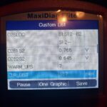
Common Live Data Parameters for LS1 Engines
- Engine RPM: Revolutions per minute of the engine.
- Engine Coolant Temperature: Temperature of the engine coolant.
- Intake Air Temperature (IAT): Temperature of the air entering the engine.
- Mass Air Flow (MAF): Amount of air entering the engine.
- Oxygen Sensor Readings: Voltage output of the oxygen sensors.
- Fuel Trims: Adjustments made by the PCM to the fuel mixture.
- Throttle Position: Percentage of throttle opening.
Troubleshooting Tips
- Verify the DTC: Ensure the DTC is valid and applicable to the vehicle.
- Check Wiring and Connections: Inspect the wiring and connections related to the affected sensor or component.
- Test Sensors: Use a multimeter to test the sensor’s voltage, resistance, and continuity.
- Check for Vacuum Leaks: Vacuum leaks can cause a variety of engine problems.
- Consult Service Manual: Refer to the vehicle’s service manual for detailed troubleshooting procedures.
4. Building Your Own LS1 OBD2 Diagnostic Port and Fuse Block
Why Build Your Own?
Building your own diagnostic port and fuse block offers several advantages:
- Customization: Tailor the setup to your specific needs.
- Cost Savings: Often cheaper than purchasing pre-made units.
- Educational Value: Provides a deeper understanding of the vehicle’s electrical system.
Required Parts for OBD2 Diagnostic Port
| Part | Vendor | Part# | Qty Needed |
|---|---|---|---|
| OBD2 Port Plastic Connector, 16 Pin | www.mouser.com | 829-12110250 | 1 |
| Terminals – for OBD2 port | www.mouser.com | 829-12129373 | 4 |
| Terminal Lock – secures terminals | www.mouser.com | 829-12160437 | 2 |
| Lamp (for check engine light) | www.allelectronics.com | check lamps/indicators, inventory changes |
Alt: Parts needed to assemble an OBD2 diagnostic port, including the connector, terminals, and terminal lock.
Required Parts for Fuse Block and Relays
| Part | Vendor | Part# | Qty Needed |
|---|---|---|---|
| Fuse Block Housing kit (terminals included) | www.rockauto.com | 85668 | 1 |
| Relay Socket | www.allelectronics.com | SRLY-2 | 2 |
| Relay 30 Amp | www.allelectronics.com | RLY-351 | 2 |
| Relay Terminal 14-18 AWG | www.mouser.com | 571-42238-2 | 8 |
Alt: Assembled fuse block with relays and wiring, ready for installation in an LS1 engine setup.
Step-by-Step Guide to Building the Fuse Block
- Prepare the Fuse Block Housing: Cut the four terminals bussed together to have three together and one separate.
- Crimp and Solder Terminals: Use terminals for heavy gauge wire and crimp and solder them as shown.
- Install Relay OUTPUT Leg: Install the terminal into the relay OUTPUT leg, and install three bussed fuse terminals into the block.
- Seat Terminals: Ensure the relay terminal and the three bussed fuse terminals are seated until they click into place.
- Install Relay INPUT Terminal: Install the relay INPUT terminal. The red wire extending up should connect to BATTERY HOT 12V+. This also supplies constant power to the fuse on the end of the block.
- Connect Gray Wire: The gray 16 AWG wire gets a terminal and is installed in the OUTPUT leg of the fuel pump relay.
- Connect Pink Wire: The other relay gets the PINK wire terminal installed in the relay coil location. This will be the KEY HOT power that activates the relay, powering up the three fuses bussed together.
- Group PINK Wires: Group the PINK wires together for the three key hot fuses.
- Install PINK Wires: Install all the PINK key hot wires into the first three fuses.
- Add ORANGE Power: Add the ORANGE battery constant power to the PCM, and a jumper to the fuel pump relay INPUT terminal.
- Install GROUND Wires: Install the GROUND for each relay coil, using a jumper from the first relay to the second. The PCM supplies 12V+ to trip the fuel pump relay.
- Install Fuel Pump Relay Control Wire: Install the Fuel Pump Relay control wire from the PCM into the relay coil terminal.
Alt: Close-up of fuse block wiring, showing the arrangement of terminals and connections for an LS1 engine.
Alt: Detailed view of the relay terminal and fuse terminals installed in the fuse block.
Alt: Relay input terminal connected to the fuse block, with the red wire extending to the battery hot 12V+.
Alt: Pink key hot wires installed into the first three fuses of the fuse block.
Alt: Orange battery constant power wire added to the PCM and fuel pump relay input terminal.
Step-by-Step Guide to Building the OBD2 Diagnostic Port
- Gather Parts: Collect all the necessary parts, including the OBD2 port plastic connector, terminals, and terminal lock.
- Insert Terminals: Insert the terminals into the appropriate pin locations on the connector.
- Secure Terminals: Use the terminal lock to secure the terminals in place.
- Wire Connections: Connect the wires to the terminals according to the OBD2 pinout diagram.
OBD2 Diagnostic Port Wiring
All OBD2 ports for LS1 and Vortec Trucks are the same.
- Pin 2: Serial Data – FROM the PCM.
- Pin 4 & 5: GROUND – Usually, only pin 5 is needed; however, some scan tools/code readers will need GROUND on pin 4 as well.
- Pin 16: 12V+ BATTERY – Power from a 12V+ Battery source.
For OBD2 LT1 96-97 ONLY, there will be additional wiring to the OBD2 port.
- Pin 6: Diagnostic Request/Field Output Enable
- Pin 9: UART Serial Data
1995 LT1 used an OBD2 port but were not OBD2 vehicles. These did not have a Serial Data on Pin 2. These used pin 9.
Wiring Tips and Best Practices
- Use Quality Wiring: Use automotive-grade wiring that is resistant to heat and chemicals.
- Crimp and Solder: Always crimp and solder connections for a secure and reliable connection.
- Label Wires: Label each wire to easily identify its function.
- Use Heat Shrink Tubing: Protect connections with heat shrink tubing.
- Double-Check Connections: Always double-check wiring connections before applying power.
5. Advanced Diagnostic Techniques for LS1 Engines
Using an Oscilloscope
An oscilloscope is a powerful tool for diagnosing electrical problems. It allows you to visualize electrical signals and identify issues such as signal noise, voltage drops, and intermittent connections.
Performing a Compression Test
A compression test measures the compression in each cylinder. Low compression can indicate worn piston rings, damaged valves, or a blown head gasket.
Performing a Leak-Down Test
A leak-down test pressurizes each cylinder with air and measures the rate of leakage. This test can help pinpoint the source of compression loss.
Checking Fuel Pressure
Proper fuel pressure is essential for correct engine operation. Use a fuel pressure gauge to check the fuel pressure at the fuel rail.
Testing Ignition Coils
Faulty ignition coils can cause misfires and poor engine performance. Use an ignition coil tester to check the output of each coil.
Using a Smoke Machine to Find Vacuum Leaks
A smoke machine introduces smoke into the intake system to find vacuum leaks. This is a quick and effective way to locate hard-to-find leaks.
6. Common Issues and Solutions with LS1 OBD2 Systems
Communication Errors
Communication errors can occur when the scan tool cannot communicate with the PCM. This can be caused by:
- Faulty Scan Tool: Try a different scan tool.
- Damaged OBD2 Port: Inspect the OBD2 port for damage or corrosion.
- Wiring Issues: Check the wiring between the OBD2 port and the PCM.
- PCM Problems: The PCM may be faulty and need to be replaced.
Incorrect Sensor Readings
Incorrect sensor readings can lead to misdiagnoses. Always verify sensor readings with a multimeter before replacing any parts.
Intermittent Problems
Intermittent problems can be challenging to diagnose. Use a scan tool to monitor live data and try to replicate the problem.
PCM Issues
The PCM is a critical component of the OBD2 system. If the PCM is faulty, it can cause a variety of problems.
7. OBD2 Scanner Recommendations for LS1 Engines
Entry-Level Scanners
Entry-level scanners are suitable for basic diagnostics and reading DTCs.
Mid-Range Scanners
Mid-range scanners offer more advanced features such as live data, graphing, and bidirectional controls.
Professional-Grade Scanners
Professional-grade scanners provide the most comprehensive diagnostic capabilities, including advanced coding, programming, and module reprogramming.
8. Maintaining Your LS1 OBD2 System
Regular Inspections
Regularly inspect the OBD2 port for damage or corrosion.
Keeping Connections Clean
Keep the OBD2 port and wiring connections clean and free of corrosion.
Updating Your Scan Tool Software
Keep your scan tool software up to date to ensure compatibility with the latest vehicles and diagnostic protocols.
Proper Storage
Store your scan tool in a safe and dry place.
9. The Future of OBD2 Technology
OBD3
OBD3 is the next generation of on-board diagnostics. It will provide even more advanced diagnostic capabilities and real-time monitoring.
Remote Diagnostics
Remote diagnostics will allow technicians to diagnose and repair vehicles remotely.
Integration with Mobile Devices
OBD2 systems will increasingly integrate with mobile devices, providing users with real-time vehicle data and diagnostic information.
10. Contact OBD2-SCANNER.EDU.VN for Expert Assistance
Navigating the complexities of LS1 OBD2 systems can be challenging. At OBD2-SCANNER.EDU.VN, we’re here to help. Whether you’re troubleshooting a specific issue or need guidance on using your OBD2 scanner, our team of experienced automotive technicians is ready to provide expert assistance.
We understand the frustrations of dealing with vehicle diagnostics, from deciphering obscure codes to identifying elusive electrical faults. That’s why we offer personalized consultations to address your unique needs and challenges.
Here’s how OBD2-SCANNER.EDU.VN can help you:
- Expert Diagnostics: We provide accurate and reliable diagnostics for LS1 engines and related systems.
- Troubleshooting Support: Our technicians can help you troubleshoot complex issues and identify the root cause of problems.
- OBD2 Scanner Guidance: We offer guidance on selecting and using the right OBD2 scanner for your needs.
- Wiring and Pinout Assistance: We can help you with wiring diagrams, pinout information, and electrical troubleshooting.
- Component Testing: We provide guidance on testing various components such as sensors, coils, and injectors.
Don’t let automotive diagnostics get you down. Contact OBD2-SCANNER.EDU.VN today for expert assistance and get back on the road with confidence.
Contact Information:
- Address: 123 Main Street, Los Angeles, CA 90001, United States
- WhatsApp: +1 (641) 206-8880
- Website: OBD2-SCANNER.EDU.VN
By understanding the LS1 OBD2 pinout and utilizing the right diagnostic tools, you can confidently tackle a wide range of automotive issues. OBD2-SCANNER.EDU.VN is committed to providing you with the knowledge and resources you need to succeed.
Frequently Asked Questions (FAQ)
What is an OBD2 scanner?
An OBD2 scanner is a diagnostic tool used to read data from a vehicle’s On-Board Diagnostics II (OBD2) system, allowing users to identify and troubleshoot various issues. According to the Environmental Protection Agency (EPA), all cars and light trucks built after 1996 are required to have an OBD2 system.
How do I read OBD2 fault codes?
To read OBD2 fault codes, connect an OBD2 scanner to the vehicle’s OBD2 port, turn on the ignition, and follow the scanner’s instructions to retrieve the diagnostic trouble codes (DTCs).
What are the common car problems and how can they be fixed?
Common car problems include engine misfires, brake issues, and electrical faults. Solutions vary depending on the problem but often involve replacing faulty components, repairing wiring, or performing maintenance tasks.
How do I troubleshoot my car?
Troubleshooting a car involves identifying the symptoms, reading diagnostic codes (if any), inspecting components, and testing systems to pinpoint the problem’s root cause.
What does the check engine light mean?
The check engine light indicates a problem with the engine or related systems. It’s essential to read the diagnostic codes to determine the specific issue.
How much does it cost to diagnose a car problem?
The cost to diagnose a car problem varies depending on the shop and the complexity of the issue. Basic diagnostic scans can range from $75 to $150, while more in-depth diagnostics may cost more.
What does OBD2 Pinout mean?
OBD2 pinout refers to the specific arrangement of pins on the OBD2 connector, each serving a different function for diagnostics and communication with the vehicle’s computer.
What is the most common cause of a check engine light?
The most common cause of a check engine light is a loose or faulty gas cap, which can trigger evaporative emission system codes.
Can I drive with the check engine light on?
Whether you can drive with the check engine light on depends on the severity of the problem. If the light is flashing, it indicates a serious issue that requires immediate attention. If the light is solid, it’s generally safe to drive, but you should still get the vehicle checked as soon as possible.
Where can I find reliable automotive diagnostic services?
Reliable automotive diagnostic services can be found at certified repair shops, dealerships, and specialized diagnostic centers. Look for technicians with ASE certification. You can also contact us at OBD2-SCANNER.EDU.VN for expert assistance.