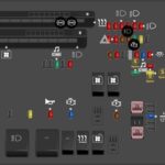
The Obd2 Port Diagram is a standardized layout of pins within the On-Board Diagnostics II (OBD2) port, which is essential for vehicle diagnostics. Understanding this layout, detailed at OBD2-SCANNER.EDU.VN, enables mechanics and car owners to accurately connect diagnostic tools, retrieve valuable data, and ensure effective vehicle maintenance using diagnostic scan tools, check engine lights and emission control systems.
Contents
- 1. Understanding the OBD2 Port Diagram
- 1.1. What is an OBD2 Port Diagram?
- 1.2. Why is the OBD2 Port Diagram Important?
- 1.3. Where Is the OBD2 Port Located?
- 2. Decoding the OBD2 Connector Pinout
- 2.1. Overview of the OBD2 Connector
- 2.2. Detailed Pinout Description
- 2.3. Variations in OBD2 Connectors
- 2.4. Reading an OBD2 Wiring Diagram
- 3. Types of OBD2 Protocols
- 3.1. Understanding OBD2 Communication Protocols
- 3.2. Key OBD2 Protocols
- 3.3. How to Identify the Protocol Used in Your Vehicle
- 3.4. Protocol Compatibility with Diagnostic Tools
- 4. Common OBD2 Port Issues and Troubleshooting
- 4.1. Identifying Common OBD2 Port Problems
- 4.2. Steps to Diagnose OBD2 Port Issues
- 4.3. Tools Needed for OBD2 Port Troubleshooting
- 4.4. How to Repair or Replace a Damaged OBD2 Port
- 5. Using an OBD2 Scanner: A Step-by-Step Guide
- 5.1. Preparing to Use an OBD2 Scanner
- 5.2. Connecting the OBD2 Scanner to the Port
- 5.3. Reading and Interpreting Diagnostic Trouble Codes (DTCs)
- 5.4. Clearing Diagnostic Trouble Codes (DTCs)
- 5.5. Live Data Monitoring
- 6. Advanced OBD2 Diagnostics
- 6.1. Understanding Freeze Frame Data
- 6.2. Using Mode 6 Data for In-Depth Analysis
- 6.3. Enhanced Diagnostics with Manufacturer-Specific Codes
- 6.4. Reprogramming and Reflashing ECUs
- 7. OBD2 Port and Vehicle Security
- 7.1. Potential Security Risks Associated with OBD2 Ports
- 7.2. Measures to Protect Your Vehicle’s OBD2 Port
- 7.3. OBD2 Port Access and Data Privacy
- 8. OBD2 and Emission Control Systems
- 8.1. The Role of OBD2 in Monitoring Emission Control Systems
- 8.2. Common Emission-Related DTCs
- 8.3. How to Use OBD2 Data to Diagnose Emission Problems
- 8.4. Ensuring Your Vehicle Meets Emission Standards
- 9. Future Trends in OBD2 Technology
- 9.1. Enhanced OBD (EOBD) and Global OBD (GOBD)
- 9.2. Wireless OBD2 Adapters and Smartphone Integration
- 9.3. Remote Diagnostics and Telematics
- 9.4. The Impact of Electric Vehicles (EVs) on OBD2 Systems
- 10. Finding Reliable OBD2 Resources and Services
- 10.1. Online Forums and Communities for OBD2 Support
- 10.2. Professional OBD2 Diagnostic Services
- 10.3. Recommended OBD2 Scan Tools and Software
- 10.4. Contact OBD2-SCANNER.EDU.VN for Expert Advice
- 11. OBD2 Port Diagram for Different Vehicle Brands
- 11.1. General OBD2 Port Diagram
- 11.2. Specific Brands and Their OBD2 Port Usage
- 11.3. Manufacturer Discretionary Pins
- 12. The Impact of SAE Standards on OBD2 Diagrams
- 12.1. Overview of SAE Standards
- 12.2. SAE J1962
- 12.3. SAE J1850
- 12.4. SAE J2284
- 12.5. Enhancing Diagnostic Capabilities
- 13. OBD2 Diagnostic Tools: Choosing the Right One
- 13.1. Types of OBD2 Scan Tools
- 13.2. Key Features to Look For
- 13.3. Top OBD2 Scan Tool Brands
- 13.4. Choosing the Right Tool for Your Needs
- 14. OBD2 and Vehicle Safety Systems
- 14.1. Integration with Safety Systems
- 14.2. Diagnosing Safety System Issues
- 14.3. Common Safety-Related DTCs
- 14.4. Ensuring Optimal Safety Performance
- 15. Navigating the OBD2 Port Diagram: A Practical Guide
- 15.1. Visual Inspection
- 15.2. Voltage Check
- 15.3. Continuity Testing
- 15.4. Protocol Verification
- 15.5. Scan Tool Connection
- 15.6. Troubleshooting Tips
- 16. OBD2 Port Diagram FAQs
- 16.1. What is an OBD2 port diagram?
- 16.2. Why is understanding the OBD2 port diagram important?
- 16.3. Where is the OBD2 port typically located in a vehicle?
- 16.4. What are the main OBD2 communication protocols?
- 16.5. How can I identify the OBD2 protocol used in my vehicle?
- 16.6. What are common issues with OBD2 ports?
- 16.7. Can I use an OBD2 scanner on any vehicle?
- 16.8. What does it mean when my OBD2 scanner shows a DTC?
- 16.9. Is it safe to clear DTCs with an OBD2 scanner?
- 16.10. How can I protect my vehicle’s OBD2 port from security risks?
1. Understanding the OBD2 Port Diagram
1.1. What is an OBD2 Port Diagram?
The OBD2 port diagram illustrates the standardized pin configuration of the OBD2 connector, also known as the J1962 connector. This diagnostic port is a crucial interface in modern vehicles, allowing technicians and vehicle owners to access the vehicle’s computer for diagnostics and troubleshooting.
1.2. Why is the OBD2 Port Diagram Important?
Understanding the OBD2 port layout is vital for several reasons:
- Accurate Diagnostics: Knowing the correct pin assignments ensures proper connection of diagnostic tools, leading to accurate and reliable data retrieval.
- Preventing Damage: Incorrect connections can damage the vehicle’s electronic systems or the diagnostic tool itself.
- Standardization: The OBD2 port’s standardized design ensures compatibility across different vehicle makes and models, simplifying the diagnostic process. According to the Society of Automotive Engineers (SAE), the standardization of OBD2 ports has greatly enhanced vehicle diagnostics.
- Emissions Testing: The OBD2 port is essential for emissions testing, ensuring vehicles meet environmental regulations.
1.3. Where Is the OBD2 Port Located?
The OBD2 port is typically located within the passenger compartment of the vehicle. Common locations include:
- Under the dashboard on the driver’s side
- Near the center console
- Behind an ashtray or small compartment
The exact location can vary by vehicle make and model, but it is generally easily accessible without tools.
2. Decoding the OBD2 Connector Pinout
2.1. Overview of the OBD2 Connector
The OBD2 connector is a 16-pin, D-shaped connector used in most modern vehicles. Each pin is assigned a specific function, enabling communication between the vehicle’s computer and external diagnostic tools.
2.2. Detailed Pinout Description
Here’s a detailed breakdown of each pin in the OBD2 connector:
| Pin Number | Description |
|---|---|
| 1 | Manufacturer Discretionary |
| 2 | SAE J1850 Bus + (VPW / PWM) |
| 3 | Manufacturer Discretionary |
| 4 | Chassis Ground |
| 5 | Signal Ground |
| 6 | CAN High (ISO 15765-4 and SAE J2284) |
| 7 | ISO 9141-2 / ISO 14230-4 K Line |
| 8 | Manufacturer Discretionary |
| 9 | Manufacturer Discretionary |
| 10 | SAE J1850 Bus – (PWM-only) |
| 11 | Manufacturer Discretionary |
| 12 | Manufacturer Discretionary |
| 13 | Manufacturer Discretionary |
| 14 | CAN Low (ISO 15765-4 and SAE J2284) |
| 15 | ISO 9141-2 / ISO 14230-4 L Line (Optional) |
| 16 | Vehicle Battery Power: – Type “A” 12V/4A – Type “B” 24V/2A |
Pin Functionalities:
- Pin 2 & 10: SAE J1850 Bus: Used primarily in older Ford vehicles, these pins facilitate communication using the SAE J1850 protocol.
- Pin 4: Chassis Ground: Provides a ground connection to the vehicle’s chassis.
- Pin 5: Signal Ground: Provides a ground reference for the electronic signals.
- Pin 6 & 14: CAN High and CAN Low: These pins are part of the Controller Area Network (CAN) bus, which is the primary communication protocol in modern vehicles. CAN bus allows various electronic control units (ECUs) to communicate with each other.
- Pin 7 & 15: ISO 9141-2 / ISO 14230-4 K and L Lines: Used in older vehicles, these pins support the ISO 9141-2 and ISO 14230-4 protocols for diagnostic communication.
- Pin 16: Vehicle Battery Power: Supplies power to the diagnostic tool, typically at 12V for Type A connectors and 24V for Type B connectors.
2.3. Variations in OBD2 Connectors
While the OBD2 standard ensures a consistent pin layout, there are some variations:
- Type A vs. Type B: Type A connectors are used in 12V systems (most passenger vehicles), while Type B connectors are used in 24V systems (heavy-duty trucks).
- Manufacturer-Specific Pins: Some manufacturers may use the discretionary pins (1, 3, 8, 9, 11, 12, and 13) for proprietary functions.
2.4. Reading an OBD2 Wiring Diagram
An OBD2 wiring diagram provides a visual representation of the connector’s pinout, showing the function of each pin and its corresponding wire color. These diagrams are essential for diagnosing electrical issues and ensuring correct connections.
3. Types of OBD2 Protocols
3.1. Understanding OBD2 Communication Protocols
OBD2 communication protocols are the languages that diagnostic tools use to communicate with a vehicle’s computer. Understanding these protocols is crucial for selecting the right diagnostic tool and interpreting the data.
3.2. Key OBD2 Protocols
The primary OBD2 protocols include:
- SAE J1850 VPW (Variable Pulse Width Modulation): Used in older GM vehicles.
- SAE J1850 PWM (Pulse Width Modulation): Used in older Ford vehicles.
- ISO 9141-2: Used in European and Asian vehicles.
- ISO 14230-4 (KWP2000): An improvement over ISO 9141-2, offering faster data transfer rates.
- SAE J2284 (CAN – Controller Area Network): The most common protocol in modern vehicles, allowing high-speed communication between various ECUs.
3.3. How to Identify the Protocol Used in Your Vehicle
Identifying the protocol used in your vehicle can be done by:
- Consulting the Vehicle’s Service Manual: The service manual typically specifies the OBD2 protocol used.
- Using an OBD2 Scanner: Some advanced OBD2 scanners can automatically detect the protocol.
- Checking the OBD2 Port: Examining which pins are populated in the OBD2 port can provide clues about the protocol used. For example, if pins 2 and 10 are populated, the vehicle likely uses SAE J1850.
3.4. Protocol Compatibility with Diagnostic Tools
Ensure that your diagnostic tool supports the OBD2 protocols used by your vehicle. Many modern scanners are multi-protocol, meaning they can communicate with vehicles using different protocols.
4. Common OBD2 Port Issues and Troubleshooting
4.1. Identifying Common OBD2 Port Problems
Several issues can affect the OBD2 port, including:
- Physical Damage: Bent or broken pins can prevent proper connection.
- Corrosion: Corrosion on the pins can disrupt electrical conductivity.
- Wiring Issues: Damaged or loose wiring can cause communication problems.
- Software Glitches: Occasionally, software glitches in the vehicle’s computer can prevent OBD2 communication.
4.2. Steps to Diagnose OBD2 Port Issues
Follow these steps to diagnose OBD2 port issues:
- Visual Inspection: Inspect the OBD2 port for any physical damage or corrosion.
- Pin Continuity Test: Use a multimeter to check the continuity of each pin, ensuring they are properly connected to the vehicle’s electrical system.
- Voltage Check: Verify that pin 16 has the correct voltage (12V or 24V) when the ignition is on.
- Wiring Inspection: Check the wiring connected to the OBD2 port for any damage or loose connections.
- Scan Tool Test: Attempt to connect a scan tool to the OBD2 port to see if it can establish communication.
4.3. Tools Needed for OBD2 Port Troubleshooting
- Multimeter: For checking voltage and continuity.
- OBD2 Scanner: To test communication with the vehicle’s computer.
- Wiring Diagram: To trace the wiring and identify any breaks or shorts.
- Contact Cleaner: To clean corroded pins.
- Pin Straightening Tool: To straighten bent pins.
4.4. How to Repair or Replace a Damaged OBD2 Port
- Cleaning: Clean corroded pins with contact cleaner.
- Straightening: Use a pin straightening tool to carefully straighten bent pins.
- Wiring Repair: Repair damaged wiring by splicing in new sections or replacing the entire wire.
- Replacement: If the OBD2 port is severely damaged, replace it with a new one. Ensure the new port is compatible with your vehicle’s make and model.
5. Using an OBD2 Scanner: A Step-by-Step Guide
5.1. Preparing to Use an OBD2 Scanner
Before using an OBD2 scanner, ensure:
- The vehicle is parked in a safe location.
- The ignition is turned on (but the engine can be off).
- You have the vehicle’s service manual for reference.
- Your OBD2 scanner is compatible with your vehicle’s make and model.
5.2. Connecting the OBD2 Scanner to the Port
- Locate the OBD2 port in your vehicle.
- Connect the OBD2 scanner to the port, ensuring a snug fit.
- Turn on the OBD2 scanner.
5.3. Reading and Interpreting Diagnostic Trouble Codes (DTCs)
- Navigate the scanner’s menu to the “Read Codes” or “Diagnostic Codes” option.
- The scanner will display any stored Diagnostic Trouble Codes (DTCs).
- Record the DTCs for further investigation.
- Use the scanner or a reference guide to look up the meaning of each DTC.
5.4. Clearing Diagnostic Trouble Codes (DTCs)
- After addressing the issue, navigate the scanner’s menu to the “Clear Codes” or “Erase Codes” option.
- Confirm that you want to clear the codes.
- The scanner will clear the DTCs, and the check engine light should turn off (if the underlying issue has been resolved).
5.5. Live Data Monitoring
OBD2 scanners can also display live data from the vehicle’s sensors, including:
- Engine RPM
- Vehicle Speed
- Coolant Temperature
- Oxygen Sensor Readings
- Fuel Trim
Monitoring live data can help diagnose intermittent issues and assess overall engine performance.
6. Advanced OBD2 Diagnostics
6.1. Understanding Freeze Frame Data
Freeze frame data captures a snapshot of the vehicle’s sensor readings at the moment a DTC was triggered. This information can be invaluable for diagnosing intermittent issues.
6.2. Using Mode 6 Data for In-Depth Analysis
Mode 6 data provides detailed information about the results of on-board diagnostic tests. This data can help identify subtle issues that may not trigger a DTC but can affect vehicle performance. According to a study by the National Institute for Automotive Service Excellence (ASE), Mode 6 data can significantly improve diagnostic accuracy.
6.3. Enhanced Diagnostics with Manufacturer-Specific Codes
While OBD2 is a standardized system, manufacturers often include proprietary codes that provide more detailed information about specific issues. Accessing these codes may require a more advanced scan tool.
6.4. Reprogramming and Reflashing ECUs
Some advanced OBD2 tools can reprogram or reflash a vehicle’s ECU. This process involves updating the ECU’s software to fix bugs, improve performance, or add new features. Reprogramming should only be performed by qualified technicians.
7. OBD2 Port and Vehicle Security
7.1. Potential Security Risks Associated with OBD2 Ports
The OBD2 port can be a potential entry point for cyberattacks. Unauthorized access to the OBD2 port can allow hackers to:
- Read sensitive vehicle data
- Modify ECU settings
- Disable vehicle functions
- Potentially even control the vehicle remotely
7.2. Measures to Protect Your Vehicle’s OBD2 Port
- Physical Security: Use a locking OBD2 port cover to prevent unauthorized access.
- Software Protection: Keep your vehicle’s software up to date to patch any security vulnerabilities.
- Awareness: Be cautious about who you allow to access your OBD2 port.
7.3. OBD2 Port Access and Data Privacy
Be aware of the data accessed through your vehicle’s OBD2 port and how it is used. Some aftermarket devices and apps may collect and transmit vehicle data without your knowledge.
8. OBD2 and Emission Control Systems
8.1. The Role of OBD2 in Monitoring Emission Control Systems
OBD2 plays a critical role in monitoring a vehicle’s emission control systems, ensuring they are functioning correctly and meeting environmental regulations.
8.2. Common Emission-Related DTCs
Common emission-related DTCs include:
- P0420: Catalyst System Efficiency Below Threshold
- P0401: Exhaust Gas Recirculation (EGR) Flow Insufficient
- P0171: System Too Lean (Bank 1)
- P0174: System Too Lean (Bank 2)
- P0442: Evaporative Emission Control System Leak Detected (Small Leak)
8.3. How to Use OBD2 Data to Diagnose Emission Problems
OBD2 data, including live sensor readings and freeze frame data, can help diagnose emission problems by:
- Identifying Faulty Sensors: Monitoring sensor readings can reveal if a sensor is malfunctioning.
- Assessing Fuel Trim: Fuel trim values can indicate lean or rich conditions, which can affect emissions.
- Evaluating Catalyst Efficiency: Oxygen sensor readings before and after the catalytic converter can assess its efficiency.
8.4. Ensuring Your Vehicle Meets Emission Standards
Regularly checking your vehicle’s OBD2 system and addressing any emission-related DTCs can help ensure your vehicle meets emission standards and avoids costly fines.
9. Future Trends in OBD2 Technology
9.1. Enhanced OBD (EOBD) and Global OBD (GOBD)
EOBD is the European version of OBD2, while GOBD aims to standardize OBD systems worldwide. These initiatives aim to improve diagnostic capabilities and ensure consistent emission control across different regions.
9.2. Wireless OBD2 Adapters and Smartphone Integration
Wireless OBD2 adapters allow you to connect your smartphone to your vehicle’s OBD2 port, enabling you to monitor vehicle data, read DTCs, and perform other diagnostic functions using a smartphone app.
9.3. Remote Diagnostics and Telematics
Remote diagnostics and telematics systems use OBD2 data to provide real-time vehicle monitoring, predictive maintenance, and other advanced services. These systems can help fleet managers optimize vehicle performance and reduce downtime.
9.4. The Impact of Electric Vehicles (EVs) on OBD2 Systems
While EVs do not have traditional combustion engines, they still have complex electronic systems that require diagnostics. OBD2 systems in EVs monitor battery health, motor performance, and other EV-specific parameters.
10. Finding Reliable OBD2 Resources and Services
10.1. Online Forums and Communities for OBD2 Support
Online forums and communities can provide valuable support and advice for OBD2 diagnostics. These forums are a great resource for troubleshooting issues, sharing tips, and learning from other vehicle owners and technicians.
10.2. Professional OBD2 Diagnostic Services
If you are not comfortable performing OBD2 diagnostics yourself, consider seeking professional help from a qualified technician. Professional diagnostic services can provide accurate and reliable diagnoses and repairs.
10.3. Recommended OBD2 Scan Tools and Software
There are many OBD2 scan tools and software options available, ranging from basic code readers to advanced diagnostic systems. Research and choose a tool that meets your specific needs and budget.
10.4. Contact OBD2-SCANNER.EDU.VN for Expert Advice
For expert advice on OBD2 diagnostics and vehicle maintenance, contact OBD2-SCANNER.EDU.VN. Our team of experienced technicians can help you troubleshoot issues, select the right tools, and ensure your vehicle is running smoothly.
11. OBD2 Port Diagram for Different Vehicle Brands
11.1. General OBD2 Port Diagram
Most vehicles adhere to a standard OBD2 port diagram as mandated by OBD2 regulations. This standardization ensures that diagnostic tools can be universally applied across different makes and models. However, some manufacturer-specific variations exist, mainly concerning the discretionary pins.
11.2. Specific Brands and Their OBD2 Port Usage
Ford:
- Uses pins 2 and 10 for SAE J1850 PWM (Pulse Width Modulation).
- Ford was an early adopter of OBD2, ensuring comprehensive diagnostics.
GM (General Motors):
- Employs pin 2 for SAE J1850 VPW (Variable Pulse Width Modulation).
- GM vehicles provide detailed diagnostic data through the OBD2 port.
Toyota:
- Typically uses pin 7 for ISO 9141-2 or ISO 14230-4 (KWP2000).
- Toyota’s implementation focuses on reliability and precision in diagnostics.
BMW:
- Often uses pin 7 for ISO 9141-2 or ISO 14230-4.
- BMW includes extensive data for engine performance and emissions.
Mercedes-Benz:
- Relies on pin 7 for ISO 9141-2 or ISO 14230-4.
- Mercedes integrates advanced diagnostic features for safety and performance systems.
Honda:
- Utilizes pin 7 for ISO 9141-2 or ISO 14230-4.
- Honda’s system provides efficient diagnostics for engine and transmission issues.
Nissan:
- Employs pin 7 for ISO 9141-2 or ISO 14230-4.
- Nissan emphasizes user-friendly diagnostic information via the OBD2 port.
Hyundai:
- Uses pin 7 for ISO 9141-2 or ISO 14230-4.
- Hyundai offers a balance of essential and advanced diagnostic data.
Chrysler/FCA (Fiat Chrysler Automobiles):
- Employs pin 2 for CCD Bus + and pin 11 for CCD Bus – in older models.
- Chrysler ensures detailed diagnostics for a wide range of vehicle systems.
11.3. Manufacturer Discretionary Pins
- Pins 1, 3, 8, 9, 11, 12, and 13 are designated as manufacturer discretionary.
- Automakers may use these pins for proprietary diagnostic or communication purposes.
- Consult the vehicle’s service manual for specific details on these pins.
12. The Impact of SAE Standards on OBD2 Diagrams
12.1. Overview of SAE Standards
SAE (Society of Automotive Engineers) standards are crucial for automotive technology, providing a framework for design, performance, and safety. Key SAE standards influencing OBD2 include J1962, J1850, and J2284.
12.2. SAE J1962
- Specifies the physical connector for the OBD2 interface.
- Ensures a standardized 16-pin layout, which simplifies diagnostic processes.
- SAE J1962 helps guarantee that diagnostic tools can interface with a variety of vehicles.
12.3. SAE J1850
- Defines communication protocols for OBD2, especially in older Ford and GM vehicles.
- Includes VPW (Variable Pulse Width Modulation) and PWM (Pulse Width Modulation) variants.
- SAE J1850 supports the transfer of diagnostic data, enhancing troubleshooting.
12.4. SAE J2284
- Standardizes the CAN (Controller Area Network) bus protocol for OBD2.
- Enables high-speed communication between a vehicle’s ECUs (Electronic Control Units).
- SAE J2284 improves real-time data transmission for enhanced diagnostics.
12.5. Enhancing Diagnostic Capabilities
- SAE standards ensure consistent diagnostic data across different vehicle makes and models.
- These standards help automotive technicians accurately diagnose and repair vehicle issues.
- Compliance with SAE standards also facilitates emissions testing and regulatory compliance.
13. OBD2 Diagnostic Tools: Choosing the Right One
13.1. Types of OBD2 Scan Tools
- Basic Code Readers:
- Affordable and user-friendly.
- Read and clear diagnostic trouble codes (DTCs).
- Enhanced Scan Tools:
- Provide live data, freeze frame information, and advanced diagnostics.
- Support manufacturer-specific codes.
- Professional Diagnostic Scanners:
- Offer comprehensive diagnostics, bi-directional controls, and ECU programming.
- Used by professional automotive technicians.
13.2. Key Features to Look For
- Protocol Compatibility:
- Ensure the tool supports the protocols used by your vehicle (CAN, ISO, SAE).
- Ease of Use:
- Choose a tool with an intuitive interface and clear instructions.
- Data Display:
- Look for real-time data, freeze frame data, and graphing capabilities.
- Update Capability:
- Select a tool with regular software updates for new vehicle models and features.
- Customer Support:
- Opt for a tool with reliable customer support and documentation.
13.3. Top OBD2 Scan Tool Brands
- Autel: Known for professional-grade scanners with advanced features.
- Launch: Offers a range of diagnostic tools for various needs and budgets.
- BlueDriver: A popular Bluetooth scanner compatible with smartphones and tablets.
- Actron: Provides reliable and affordable code readers for DIYers.
13.4. Choosing the Right Tool for Your Needs
- DIY Enthusiasts:
- A basic code reader or enhanced scan tool may suffice.
- Focus on ease of use and essential features.
- Professional Technicians:
- Invest in a professional diagnostic scanner for comprehensive capabilities.
- Prioritize advanced features, bi-directional controls, and ECU programming.
14. OBD2 and Vehicle Safety Systems
14.1. Integration with Safety Systems
OBD2 is integrated with various vehicle safety systems, including:
- ABS (Anti-lock Braking System): Monitors brake performance and detects wheel lock-up.
- SRS (Supplemental Restraint System): Detects airbag deployment and related faults.
- Traction Control System (TCS): Monitors wheel slip and adjusts engine power.
- Electronic Stability Control (ESC): Enhances vehicle stability by detecting and correcting skids.
14.2. Diagnosing Safety System Issues
OBD2 can help diagnose issues with safety systems by:
- Reading diagnostic trouble codes (DTCs) related to safety system faults.
- Providing live data from sensors and actuators.
- Enabling technicians to identify and address safety-related issues.
14.3. Common Safety-Related DTCs
- C0031: Left Front Wheel Speed Sensor Circuit Malfunction (ABS)
- B0001: Driver Airbag Deployment Loop Open Circuit (SRS)
- C1214: System Relay Circuit Open or Shorted (TCS)
- C1210: Yaw Rate Sensor Malfunction (ESC)
14.4. Ensuring Optimal Safety Performance
Regularly checking your vehicle’s OBD2 system and addressing safety-related DTCs can help ensure that your vehicle’s safety systems are functioning correctly. This proactive approach enhances overall vehicle safety and reduces the risk of accidents.
15. Navigating the OBD2 Port Diagram: A Practical Guide
15.1. Visual Inspection
- Inspect the OBD2 port for any physical damage, such as bent or broken pins.
- Check for corrosion or debris inside the connector.
15.2. Voltage Check
- Use a multimeter to check the voltage at pin 16. It should read approximately 12V (or 24V for heavy-duty vehicles) with the ignition on.
- Verify the ground connections at pins 4 and 5.
15.3. Continuity Testing
- Use a multimeter to check the continuity of each pin, ensuring they are properly connected to the vehicle’s electrical system.
- Refer to the vehicle’s wiring diagram for accurate pin assignments.
15.4. Protocol Verification
- Identify the OBD2 protocol used by your vehicle (CAN, ISO, SAE).
- Ensure your diagnostic tool supports the correct protocol.
15.5. Scan Tool Connection
- Connect your OBD2 scan tool to the port, ensuring a secure fit.
- Turn on the scan tool and follow the manufacturer’s instructions for reading DTCs and live data.
15.6. Troubleshooting Tips
- If the scan tool fails to connect, double-check the voltage and ground connections.
- Inspect the wiring harness for any damage or loose connections.
- Consult online forums and communities for OBD2 support.
16. OBD2 Port Diagram FAQs
16.1. What is an OBD2 port diagram?
An OBD2 port diagram illustrates the pin configuration of the OBD2 connector, crucial for connecting diagnostic tools and accessing vehicle data.
16.2. Why is understanding the OBD2 port diagram important?
Understanding the diagram ensures accurate diagnostics, prevents damage, and maintains compatibility across vehicle models.
16.3. Where is the OBD2 port typically located in a vehicle?
It’s usually under the dashboard on the driver’s side, near the center console, or behind a compartment.
16.4. What are the main OBD2 communication protocols?
Key protocols include SAE J1850 VPW/PWM, ISO 9141-2, ISO 14230-4 (KWP2000), and SAE J2284 (CAN).
16.5. How can I identify the OBD2 protocol used in my vehicle?
Consult the vehicle’s service manual, use an OBD2 scanner, or check which pins are populated in the OBD2 port.
16.6. What are common issues with OBD2 ports?
Common issues include physical damage, corrosion, wiring problems, and software glitches.
16.7. Can I use an OBD2 scanner on any vehicle?
Most OBD2 scanners are compatible with vehicles manufactured after 1996 in the US, but always verify compatibility.
16.8. What does it mean when my OBD2 scanner shows a DTC?
A DTC (Diagnostic Trouble Code) indicates a specific issue detected by the vehicle’s onboard computer.
16.9. Is it safe to clear DTCs with an OBD2 scanner?
Yes, but only after addressing the underlying issue to prevent it from recurring.
16.10. How can I protect my vehicle’s OBD2 port from security risks?
Use a locking OBD2 port cover, keep vehicle software updated, and be cautious about who accesses the port.
The OBD2 port is your car’s gateway to revealing its secrets, and at OBD2-SCANNER.EDU.VN, we’re dedicated to helping you understand it. By exploring this information and grasping the significance of the OBD2 port diagram, you can confidently tackle automotive diagnostics and maintenance. You’re now equipped to read vehicle data effectively, troubleshoot potential issues, and ensure your vehicle operates smoothly and efficiently. Don’t hesitate to contact us at 123 Main Street, Los Angeles, CA 90001, United States, via Whatsapp at +1 (641) 206-8880, or visit our website at OBD2-SCANNER.EDU.VN for expert guidance and top-notch service.