Pinout and make your own OBD2 to USB cable is possible with the right tools and knowledge, allowing you to interface with your vehicle’s computer for diagnostics and data logging. OBD2-SCANNER.EDU.VN provides comprehensive guides and resources to help you successfully create your own cable and unlock the potential of your vehicle’s onboard diagnostics. By understanding the OBD2 pinout and following a detailed process, you can create a custom cable for efficient vehicle communication and diagnostics.
Contents
- 1. Understanding the OBD2 Protocol and Pinout
- 1.1. Key OBD2 Pins and Their Functions
- 1.2. Communication Protocols Used in OBD2
- 2. Gathering the Necessary Tools and Parts
- 2.1. Essential Tools
- 2.2. Required Parts
- 2.3. Where to Source Components
- 3. Step-by-Step Guide to Pinout Your Own OBD2 to USB Cable
- 3.1. Identifying the Correct OBD2 Pins
- 3.2. Preparing the Wires
- 3.3. Connecting Wires to the OBD2 Connector
- 3.4. Connecting Wires to the USB Connector
- 3.5. Testing the Cable
- 4. Advanced Tips for OBD2 to USB Cable Construction
- 4.1. Using Shielded Cable
- 4.2. Adding a Fuse
- 4.3. Incorporating an LED Indicator
- 5. Troubleshooting Common Issues
- 5.1. Cable Not Recognized by Computer
- 5.2. No Data from Vehicle
- 5.3. Intermittent Connection
- 6. Software and Applications for OBD2 Data
- 6.1. Popular OBD2 Software Options
- 6.2. Setting Up Software for Use with Your Cable
- 6.3. Interpreting OBD2 Data
- 7. Safety Precautions
- 7.1. Disconnecting the Battery
- 7.2. Avoiding Short Circuits
- 7.3. Handling Vehicle Electronics with Care
- 8. Understanding J2534 Pass-Thru Devices
- 8.1. What is a J2534 Pass-Thru Device?
- 8.2. How J2534 Devices Differ from Basic OBD2 Cables
- 8.3. When to Use a J2534 Device Instead of a DIY Cable
- 9. Legal and Ethical Considerations
- 9.1. Data Privacy
- 9.2. Vehicle Warranties
- 9.3. Ethical Use of Diagnostic Information
- 10. The Future of OBD and Vehicle Diagnostics
- 10.1. Advancements in OBD Technology
- 10.2. The Role of DIY Diagnostics in the Future
- 10.3. The Impact of Electric Vehicles on OBD Systems
- FAQ: Making Your Own OBD2 to USB Cable
- 1. What is an OBD2 to USB cable?
- 2. Why would I want to make my own OBD2 to USB cable?
- 3. What are the risks of making my own OBD2 to USB cable?
- 4. What tools do I need to make an OBD2 to USB cable?
- 5. How do I determine the correct pinout for my OBD2 cable?
- 6. Can I use any USB connector for this project?
- 7. What type of wire should I use for making the cable?
- 8. How do I test the cable after making it?
- 9. What software can I use with my DIY OBD2 to USB cable?
- 10. Where can I get help if I run into problems?
1. Understanding the OBD2 Protocol and Pinout
What is the OBD2 protocol and why is understanding the pinout essential? The On-Board Diagnostics II (OBD2) protocol is a standardized system used in modern vehicles to monitor and report on various engine and vehicle parameters. According to the Environmental Protection Agency (EPA), OBD2 was mandated in all cars and light trucks sold in the United States starting in 1996 to ensure emissions compliance. Understanding the OBD2 pinout is essential because it allows you to correctly connect to your vehicle’s diagnostic system and retrieve valuable data.
1.1. Key OBD2 Pins and Their Functions
Which are the key OBD2 pins, and what are their functions? The OBD2 connector has 16 pins, each with a specific function. Here are some of the key pins:
- Pin 4: Chassis Ground
- Pin 5: Signal Ground
- Pin 6: CAN High (J-2284)
- Pin 7: K-Line (ISO 9141-2 and ISO 14230-4)
- Pin 10: J1850 Bus (-)
- Pin 14: CAN Low (J-2284)
- Pin 15: L-Line (ISO 9141-2 and ISO 14230-4)
- Pin 16: Battery Power
Understanding these pin functions is crucial for creating a functional OBD2 to USB cable. Improper connections can lead to diagnostic failures or, in severe cases, damage to the vehicle’s ECU.
1.2. Communication Protocols Used in OBD2
What communication protocols are used in OBD2, and how do they affect cable design? Several communication protocols are used in OBD2, including:
- CAN (Controller Area Network): The most common protocol in modern vehicles, offering high-speed communication.
- ISO 9141-2: Used in older vehicles, primarily European models.
- ISO 14230-4 (KWP2000): Another protocol used in older vehicles.
- J1850 VPW and PWM: Used primarily in older Ford and GM vehicles.
The choice of protocol affects the cable design because different protocols require different pin configurations. For instance, CAN communication uses pins 6 and 14, while ISO 9141-2 uses pins 7 and 15.
2. Gathering the Necessary Tools and Parts
What tools and parts are required to pinout and make your own OBD2 to USB cable? To successfully create your own OBD2 to USB cable, you’ll need the following tools and parts:
2.1. Essential Tools
What are the essential tools for making an OBD2 to USB cable?
- Wire Strippers/Cutters: For stripping and cutting wires to the correct length.
- Needle-Nose Pliers: For manipulating small components and wires.
- Soldering Iron and Solder: To create secure and reliable connections (recommended).
- Multimeter: To test the continuity and voltage of the connections.
- Crimping Tool: For attaching pins to the wires (Molex crimping tool recommended for certain connectors).
2.2. Required Parts
Which parts are required to assemble the OBD2 to USB cable?
- OBD2 Connector: A 16-pin female OBD2 connector to plug into your vehicle.
- USB Connector: A USB Type-A connector to plug into your computer.
- Wires: Stranded copper wires of appropriate gauge (22-26 AWG recommended) for connecting the OBD2 and USB connectors.
- 4-Pin Connector (Optional): Can be used to simplify the connection between the OBD2 and USB wires.
- Heat Shrink Tubing: To insulate and protect the solder joints.
2.3. Where to Source Components
Where can you source the necessary components for your OBD2 to USB cable? You can source these components from various online retailers and electronic supply stores. Some popular options include:
- Amazon: Offers a wide variety of OBD2 connectors, USB connectors, and wiring supplies.
- eBay: A good source for finding individual components and kits.
- Digi-Key Electronics: An electronics distributor that specializes in electronic components.
- Mouser Electronics: Another reputable electronics distributor with a vast selection of parts.
3. Step-by-Step Guide to Pinout Your Own OBD2 to USB Cable
How can you pinout and make your own OBD2 to USB cable following a step-by-step guide? Follow these steps to create your own OBD2 to USB cable:
3.1. Identifying the Correct OBD2 Pins
How do you identify the correct OBD2 pins for your specific vehicle and diagnostic needs? Begin by identifying the specific OBD2 pins that you need for your vehicle and diagnostic purposes. This typically includes:
- Pin 4: Chassis Ground
- Pin 6: CAN High
- Pin 14: CAN Low
- Pin 16: Battery Power
Consult your vehicle’s service manual or an online OBD2 pinout database to confirm the correct pins.
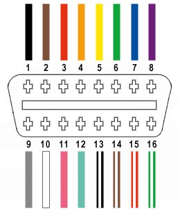 Identifying Correct OBD2 Pins
3.2. Preparing the Wires
How do you prepare the wires for connecting to the OBD2 and USB connectors? Prepare the wires by cutting them to the appropriate length and stripping the ends. Use wire strippers to carefully remove the insulation without damaging the wire.
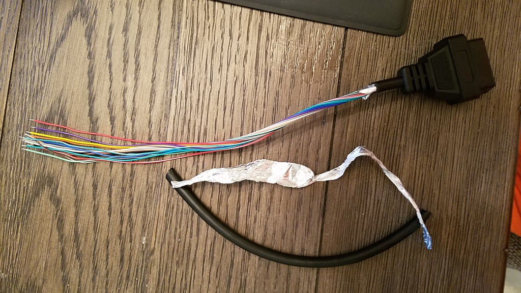 Stripped Sheath and Shielding
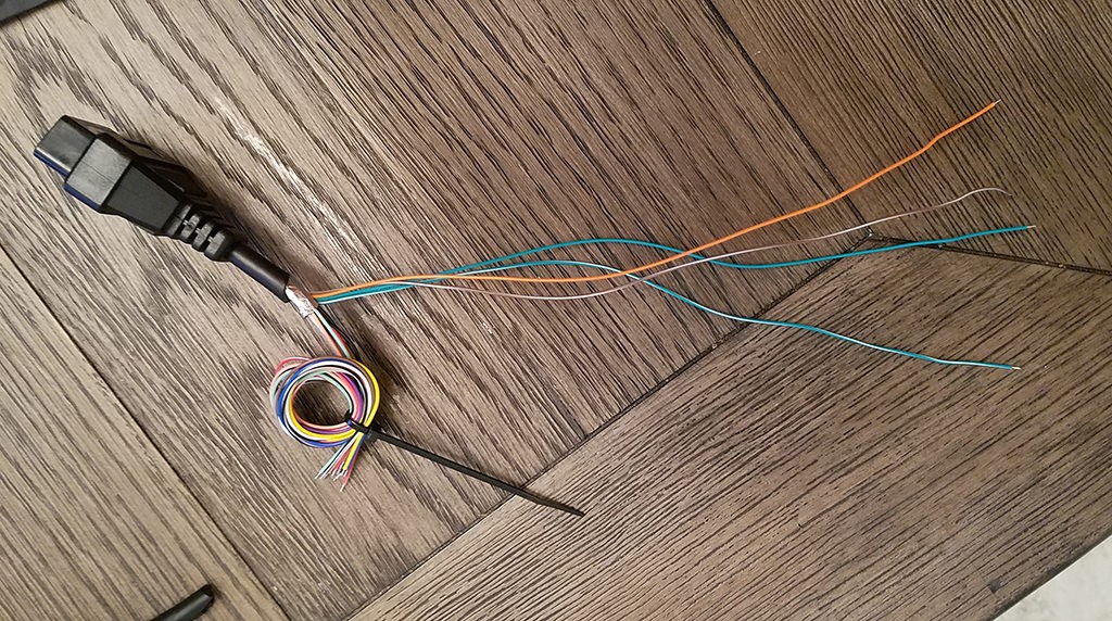 Separated 4 Wires Being Used
3.3. Connecting Wires to the OBD2 Connector
How do you connect the prepared wires to the OBD2 connector? Connect the prepared wires to the OBD2 connector using soldering or crimping.
Soldering:
- Tin the ends of the wires with solder.
- Solder the wires to the corresponding pins on the OBD2 connector.
- Use heat shrink tubing to insulate the solder joints.
Crimping:
- Attach crimp pins to the ends of the wires using a crimping tool.
- Insert the crimp pins into the corresponding slots in the OBD2 connector.
3.4. Connecting Wires to the USB Connector
How do you connect the wires from the OBD2 connector to the USB connector? Connect the wires from the OBD2 connector to the USB connector. The typical USB pinout is as follows:
- Pin 1: VCC (5V)
- Pin 2: Data –
- Pin 3: Data +
- Pin 4: Ground
Connect the OBD2 wires to the USB connector pins as follows:
- OBD2 Pin 16 (Battery Power) to USB Pin 1 (VCC)
- OBD2 Pin 6 (CAN High) to USB Pin 3 (Data +)
- OBD2 Pin 14 (CAN Low) to USB Pin 2 (Data -)
- OBD2 Pin 4 (Chassis Ground) to USB Pin 4 (Ground)
Use soldering or crimping to make the connections, and insulate the joints with heat shrink tubing.
3.5. Testing the Cable
How should you test the finished OBD2 to USB cable to ensure it works correctly? Test the cable using a multimeter to check for continuity between the corresponding pins. Ensure that there are no shorts or open circuits. Once you confirm that the wiring is correct, plug the cable into your vehicle and computer to test its functionality with diagnostic software.
4. Advanced Tips for OBD2 to USB Cable Construction
What are some advanced tips to improve your OBD2 to USB cable construction?
4.1. Using Shielded Cable
Why should you use shielded cable, and how does it improve performance? Using shielded cable can help reduce electromagnetic interference and improve the reliability of the connection. Shielded cable has a layer of conductive material (usually aluminum foil or braided copper) that surrounds the wires and protects them from external noise.
4.2. Adding a Fuse
Why is adding a fuse recommended, and how do you implement it? Adding a fuse to the power line (Pin 16) can protect your vehicle’s ECU from overcurrent. A 1-amp fuse is generally sufficient. Inline fuse holders make it easy to add a fuse to your cable.
4.3. Incorporating an LED Indicator
How can you incorporate an LED indicator to show cable activity? Incorporating an LED indicator can provide visual feedback on cable activity. Connect an LED and a resistor (e.g., 470 ohms) in series between the power and ground lines. The LED will light up when the cable is powered.
5. Troubleshooting Common Issues
What are some common issues encountered when making an OBD2 to USB cable, and how can you troubleshoot them?
5.1. Cable Not Recognized by Computer
What should you do if your computer does not recognize the OBD2 to USB cable? If your computer does not recognize the cable, check the following:
- Wiring: Ensure that all wires are connected to the correct pins.
- USB Port: Try a different USB port on your computer.
- Drivers: Make sure you have the necessary drivers installed for your USB interface.
- Continuity: Use a multimeter to check for continuity between the USB and OBD2 connectors.
5.2. No Data from Vehicle
What should you do if you are not receiving any data from the vehicle after connecting the cable? If you are not receiving data from the vehicle, check the following:
- OBD2 Connection: Ensure that the OBD2 connector is securely plugged into your vehicle’s diagnostic port.
- Power: Verify that Pin 16 (Battery Power) has a good connection.
- Protocol: Confirm that your diagnostic software is using the correct communication protocol for your vehicle.
- ECU Compatibility: Ensure that your vehicle’s ECU supports the diagnostic functions you are trying to access.
5.3. Intermittent Connection
What causes an intermittent connection, and how can you fix it? An intermittent connection can be caused by loose wiring or poor solder joints. Check all connections to ensure they are secure. Use a multimeter to test for continuity while gently wiggling the wires to identify any weak points.
6. Software and Applications for OBD2 Data
Which software and applications can be used to read and interpret OBD2 data?
6.1. Popular OBD2 Software Options
Which are some popular OBD2 software options for reading and interpreting vehicle data? Several software options are available for reading and interpreting OBD2 data. Some popular choices include:
- FORScan: A powerful software for Ford, Lincoln, and Mercury vehicles.
- OBD Auto Doctor: A user-friendly software that supports multiple platforms.
- Torque Pro (Android): A popular app for Android devices that provides real-time data and diagnostic information.
- DashCommand: A versatile app for iOS and Android that offers a wide range of features.
6.2. Setting Up Software for Use with Your Cable
How do you set up your chosen software to work with your custom OBD2 to USB cable? Set up your software by selecting the correct communication port and protocol. Most software will automatically detect the OBD2 adapter, but you may need to manually configure the settings in some cases. Consult the software’s documentation for detailed instructions.
6.3. Interpreting OBD2 Data
How do you interpret the data received from your vehicle’s OBD2 system? Interpreting OBD2 data involves understanding the various parameters and diagnostic trouble codes (DTCs) that your vehicle reports. Some common parameters include:
- Engine RPM: Revolutions per minute of the engine.
- Vehicle Speed: Current speed of the vehicle.
- Coolant Temperature: Temperature of the engine coolant.
- Intake Air Temperature: Temperature of the air entering the engine.
- Mass Air Flow (MAF): Amount of air entering the engine.
- Oxygen Sensor Readings: Readings from the oxygen sensors in the exhaust system.
DTCs are codes that indicate specific problems with the vehicle. These codes can be used to diagnose and repair various issues. Refer to an OBD2 code database or your vehicle’s service manual to interpret the DTCs.
7. Safety Precautions
What safety precautions should you take when working with OBD2 systems and vehicle electronics?
7.1. Disconnecting the Battery
Why is it recommended to disconnect the battery before working on vehicle electronics? It is recommended to disconnect the battery before working on vehicle electronics to prevent electrical shorts and potential damage to the ECU.
7.2. Avoiding Short Circuits
How can you avoid short circuits when creating your OBD2 to USB cable? Avoid short circuits by carefully insulating all connections and using heat shrink tubing to protect solder joints. Double-check your wiring before connecting the cable to your vehicle.
7.3. Handling Vehicle Electronics with Care
How should you handle vehicle electronics to prevent damage? Handle vehicle electronics with care to prevent damage. Avoid static electricity by grounding yourself before touching any electronic components. Do not force any connections, and always refer to your vehicle’s service manual for guidance.
8. Understanding J2534 Pass-Thru Devices
What are J2534 pass-thru devices, and how do they relate to OBD2 to USB cables?
8.1. What is a J2534 Pass-Thru Device?
What is the purpose of a J2534 pass-thru device, and how does it work? A J2534 pass-thru device is a tool that allows a computer to communicate with a vehicle’s ECU using a standardized interface. According to the EPA, J2534 devices are required for reprogramming vehicle ECUs to comply with emissions regulations. These devices act as a bridge between the computer and the vehicle, allowing technicians to perform diagnostics, programming, and other advanced functions.
8.2. How J2534 Devices Differ from Basic OBD2 Cables
How do J2534 devices differ from basic OBD2 cables in terms of functionality and capabilities? J2534 devices offer more advanced functionality compared to basic OBD2 cables. While basic cables are primarily used for reading diagnostic data and clearing trouble codes, J2534 devices can perform ECU reprogramming, advanced diagnostics, and other specialized functions. J2534 devices also support a wider range of communication protocols and vehicle makes.
8.3. When to Use a J2534 Device Instead of a DIY Cable
When is it more appropriate to use a J2534 device instead of a DIY OBD2 to USB cable? It is more appropriate to use a J2534 device instead of a DIY cable when you need to perform advanced functions such as ECU reprogramming, module configuration, or access manufacturer-specific diagnostic procedures. DIY cables are suitable for basic diagnostics and data logging, but they lack the advanced capabilities of J2534 devices.
9. Legal and Ethical Considerations
What are the legal and ethical considerations when accessing and using OBD2 data?
9.1. Data Privacy
What are the data privacy implications of accessing your vehicle’s OBD2 data? Accessing your vehicle’s OBD2 data raises data privacy concerns. The data collected by OBD2 systems can include information about your driving habits, vehicle location, and other personal information. Be aware of how this data is being used and who has access to it.
9.2. Vehicle Warranties
How can modifying or accessing your vehicle’s OBD2 system affect your warranty? Modifying or accessing your vehicle’s OBD2 system can affect your warranty. Some manufacturers may void the warranty if they determine that modifications to the OBD2 system have caused damage to the vehicle. Check your warranty terms and conditions before making any modifications.
9.3. Ethical Use of Diagnostic Information
How should you ethically use the diagnostic information obtained from your vehicle? Use diagnostic information ethically by only accessing data from your own vehicles or with the owner’s permission. Do not use diagnostic information to tamper with vehicle systems or to violate any laws or regulations.
10. The Future of OBD and Vehicle Diagnostics
What does the future hold for OBD and vehicle diagnostics?
10.1. Advancements in OBD Technology
What are some potential advancements in OBD technology? Advancements in OBD technology include:
- Enhanced Data Collection: More detailed and comprehensive data collection for improved diagnostics and performance monitoring.
- Wireless Communication: Increased use of wireless communication technologies such as Bluetooth and Wi-Fi for easier data access and transfer.
- Cloud-Based Diagnostics: Integration with cloud-based platforms for remote diagnostics and predictive maintenance.
- Cybersecurity Enhancements: Improved cybersecurity measures to protect vehicle systems from hacking and unauthorized access.
10.2. The Role of DIY Diagnostics in the Future
How will DIY diagnostics evolve in the future? DIY diagnostics will likely become more accessible and user-friendly in the future. With the increasing availability of affordable diagnostic tools and software, more vehicle owners will be able to perform basic diagnostics and maintenance tasks themselves. This trend will empower vehicle owners to take better care of their vehicles and reduce their reliance on professional mechanics for routine maintenance.
10.3. The Impact of Electric Vehicles on OBD Systems
How are electric vehicles impacting OBD systems and diagnostic procedures? Electric vehicles (EVs) are impacting OBD systems by introducing new parameters and diagnostic codes related to the electric powertrain. EVs require specialized diagnostic tools and procedures to monitor the battery pack, electric motors, and other unique components. As EVs become more prevalent, OBD systems will need to adapt to accommodate the specific needs of these vehicles.
As you can see, pinout and make your own OBD2 to USB cable is an achievable project that can provide valuable insights into your vehicle’s operation. By following this comprehensive guide and using the resources available at OBD2-SCANNER.EDU.VN, you can successfully create your own cable and unlock the potential of your vehicle’s onboard diagnostics.
Experiencing challenges in diagnosing your vehicle or need expert guidance on using OBD2 scanners? Contact us today for personalized assistance. Our team at OBD2-SCANNER.EDU.VN is ready to help you understand your vehicle better and perform effective repairs. Reach out now via Whatsapp at +1 (641) 206-8880 or visit our location at 123 Main Street, Los Angeles, CA 90001, United States. You can also explore more on our website: OBD2-SCANNER.EDU.VN. Let us help you keep your vehicle running smoothly!
FAQ: Making Your Own OBD2 to USB Cable
1. What is an OBD2 to USB cable?
An OBD2 to USB cable is a specialized cable that allows you to connect your vehicle’s On-Board Diagnostics II (OBD2) port to a computer via USB. This connection enables you to read diagnostic data, monitor vehicle performance, and perform other functions using diagnostic software.
2. Why would I want to make my own OBD2 to USB cable?
Making your own OBD2 to USB cable can be a cost-effective alternative to purchasing a pre-made cable. It also allows you to customize the cable to your specific needs and learn more about vehicle diagnostics.
3. What are the risks of making my own OBD2 to USB cable?
The risks include incorrect wiring, which can damage your vehicle’s ECU or your computer. It’s crucial to follow the correct pinout and take proper safety precautions.
4. What tools do I need to make an OBD2 to USB cable?
Essential tools include wire strippers, a soldering iron, a multimeter, and a crimping tool. You’ll also need an OBD2 connector, a USB connector, and appropriate gauge wires.
5. How do I determine the correct pinout for my OBD2 cable?
Consult your vehicle’s service manual or an online OBD2 pinout database to confirm the correct pins for your specific vehicle and diagnostic needs.
6. Can I use any USB connector for this project?
You should use a standard USB Type-A connector for connecting to your computer. Ensure that the connector is of good quality to provide a stable connection.
7. What type of wire should I use for making the cable?
Use stranded copper wires of appropriate gauge (22-26 AWG recommended) for connecting the OBD2 and USB connectors.
8. How do I test the cable after making it?
Test the cable using a multimeter to check for continuity between the corresponding pins. Ensure that there are no shorts or open circuits before plugging it into your vehicle.
9. What software can I use with my DIY OBD2 to USB cable?
Popular software options include FORScan, OBD Auto Doctor, Torque Pro (Android), and DashCommand.
10. Where can I get help if I run into problems?
You can find help online through forums, DIY communities, and automotive diagnostic websites. Additionally, OBD2-SCANNER.EDU.VN offers resources and support for creating and using OBD2 cables.