Connecting a CAN bus to an Arduino using the Sparkfun OBD2 UART can empower you to tap into your vehicle’s data, offering insights into its performance and health. This guide, brought to you by OBD2-SCANNER.EDU.VN, explores the process, potential pitfalls, and solutions for seamless integration, enhancing your automotive diagnostics and customization projects. Learn how to retrieve real-time vehicle data and create custom dashboards, monitor engine performance, and troubleshoot potential issues with your vehicle.
Contents
- 1. What Is CAN Bus And Why Use It With Arduino?
- 2. Understanding The Sparkfun OBD2 UART Board
- 3. Essential Components For Connecting CAN Bus To Arduino
- 4. Wiring The Sparkfun OBD2 UART To Arduino
- 5. Arduino Code For Reading CAN Bus Data
- 6. Common Problems And Troubleshooting Tips
- 7. Advanced Techniques For CAN Bus Integration
- 8. Choosing The Right OBD2 PIDs
- 9. Integrating With Other Sensors And Systems
- 10. Case Studies: Real-World Applications
- 11. Safety Considerations When Working With OBD2
- 12. Alternatives To Sparkfun OBD2 UART
- 13. Understanding OBD2 Protocols
- 14. Data Interpretation And Units
- 15. Power Consumption And Management
- 16. Legal And Ethical Considerations
- 17. The Future Of CAN Bus And Arduino
- 18. Resources For Further Learning
- 19. Frequently Asked Questions (FAQ)
- 19.1. What is an OBD2 scanner?
- 19.2. How do I read OBD2 fault codes?
- 19.3. What are common car errors and how can they be fixed?
- 19.4. Can I use any Arduino board with the Sparkfun OBD2 UART?
- 19.5. What baud rate should I use for serial communication?
- 19.6. How do I know if my vehicle supports a specific PID?
- 19.7. What does a “NO DATA” response mean?
- 19.8. Can I damage my vehicle by using an OBD2 scanner?
- 19.9. Where is the OBD2 port located in my car?
- 19.10. How can I clear the check engine light?
- 20. Connect With OBD2-SCANNER.EDU.VN For Expert Assistance
1. What Is CAN Bus And Why Use It With Arduino?
CAN bus (Controller Area Network) is a robust communication protocol widely used in vehicles to allow different microcontrollers to communicate with each other without a host computer. Using CAN bus with Arduino opens up possibilities for real-time vehicle monitoring and customization. According to a study by the University of Michigan’s Transportation Research Institute in 2022, CAN bus allows data exchange rates up to 1 Mbps, making it suitable for various automotive applications.
- Real-time data access: Access engine RPM, vehicle speed, temperature, and more.
- Custom dashboards: Create personalized displays for vital vehicle information.
- Performance monitoring: Track vehicle performance and identify potential issues early.
- DIY car projects: Build your own vehicle automation and monitoring systems.
2. Understanding The Sparkfun OBD2 UART Board
The Sparkfun OBD2 UART board acts as a bridge between your vehicle’s OBD2 port and your Arduino, simplifying access to CAN bus data. It translates the complex CAN bus protocol into a simpler serial UART (Universal Asynchronous Receiver/Transmitter) format that Arduino can easily understand.
- Simplified Interface: Converts CAN bus data to serial UART for easy Arduino integration.
- Standard OBD2 Connection: Connects directly to your vehicle’s OBD2 port.
- Voltage Compatibility: Operates at 3.3V, making it compatible with most Arduino boards.
- Built-in CAN Controller: Handles the low-level CAN bus communication details.
3. Essential Components For Connecting CAN Bus To Arduino
To get started, you’ll need a few key components. Here’s a breakdown:
- Arduino Board: An Arduino Uno, Nano, or Mega will work.
- Sparkfun OBD2 UART Board: The interface for CAN bus communication.
- OBD2 Cable: To connect the Sparkfun board to your vehicle.
- Jumper Wires: For connecting the Sparkfun board to the Arduino.
- Power Supply: Usually, the Arduino’s USB connection is sufficient.
- Optional LCD Screen: For displaying the data (like the 16×2 LCD mentioned).
4. Wiring The Sparkfun OBD2 UART To Arduino
Connecting the Sparkfun OBD2 UART to your Arduino involves a few simple wiring steps. Ensuring correct connections is crucial for successful communication.
- Connect OBD2 TX to Arduino RX: This is the transmit line from the OBD2 UART to the Arduino’s receive line.
- Connect OBD2 RX to Arduino TX: This is the receive line from the OBD2 UART to the Arduino’s transmit line.
- Connect OBD2 GND to Arduino GND: This provides a common ground for both devices.
- Connect OBD2 VCC to Arduino 5V (or 3.3V): Depending on your Arduino and Sparkfun board, this provides power to the OBD2 UART. Be sure to check the voltage requirements of your Sparkfun board to avoid damage.
 Wiring diagram of Sparkfun OBD2 UART to Arduino
5. Arduino Code For Reading CAN Bus Data
The following code provides a basic framework for reading data from the Sparkfun OBD2 UART and displaying it on an LCD. This code can be modified to suit your specific needs and vehicle.
#include <SoftwareSerial.h>
#include <LiquidCrystal.h>
// Define LCD pins
const int rs = 12, en = 11, d4 = 5, d5 = 4, d6 = 3, d7 = 2;
LiquidCrystal lcd(rs, en, d4, d5, d6, d7);
// Define software serial pins for OBD2 UART
SoftwareSerial obdSerial(10, 9); // RX, TX
char rxData[20];
byte rxIndex = 0;
int vehicleSpeed = 0;
int vehicleRPM = 0;
void setup() {
// Initialize LCD
lcd.begin(16, 2);
lcd.print("Initializing...");
// Initialize OBD2 UART serial communication
obdSerial.begin(9600);
delay(1000);
lcd.clear();
lcd.print("OBD2 Ready");
delay(1000);
}
void loop() {
// Request vehicle speed (PID 010D)
getOBDData("010D", vehicleSpeed);
// Request engine RPM (PID 010C)
getOBDData("010C", vehicleRPM);
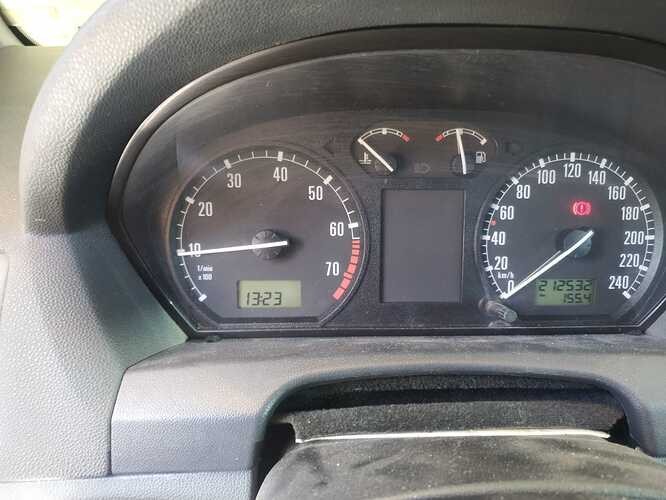
// Display data on LCD
lcd.clear();
lcd.setCursor(0, 0);
lcd.print("Speed: ");
lcd.print(vehicleSpeed);
lcd.print(" km/h");
lcd.setCursor(0, 1);
lcd.print("RPM: ");
lcd.print(vehicleRPM);
delay(200);
}
void getOBDData(String pid, int &data) {
// Clear receive buffer
memset(rxData, 0, sizeof(rxData));
rxIndex = 0;
// Send PID command
obdSerial.println(pid);
// Read response
getResponse();
// Parse data
if (rxData[0] == '4' && rxData[1] == '1') { // Check for valid response
if (pid == "010D") {
data = strtol(&rxData[6], 0, 16);
} else if (pid == "010C") {
data = ((strtol(&rxData[6], 0, 16) * 256) + strtol(&rxData[9], 0, 16)) / 4;
}
} else {
data = -1; // Indicate error
}
}
void getResponse() {
char inChar;
while (true) {
if (obdSerial.available() > 0) {
inChar = obdSerial.read();
if (inChar == '>') break; // Stop at prompt
if (rxIndex < sizeof(rxData) - 1) {
rxData[rxIndex++] = inChar;
}
}
}
rxData[rxIndex] = ''; // Null-terminate the string
}- Include Libraries: Includes the necessary libraries for serial communication and LCD control.
- Define LCD Pins: Specifies the Arduino pins connected to the LCD.
- Initialize Serial Communication: Sets up serial communication with the Sparkfun OBD2 UART.
- Request Data: Sends OBD2 PID (Parameter ID) commands to request specific data.
- Parse Response: Reads and parses the response from the OBD2 UART.
- Display Data: Shows the parsed data on the LCD screen.
6. Common Problems And Troubleshooting Tips
Connecting CAN bus to Arduino isn’t always smooth sailing. Here are some common issues and how to troubleshoot them.
- No Data Received:
- Check Wiring: Ensure all connections are correct and secure.
- Verify Baud Rate: Make sure the baud rate in your Arduino code matches the Sparkfun OBD2 UART’s baud rate (usually 9600).
- Test with AT Commands: Use a serial monitor to send AT commands (like “ATZ” for reset) to the Sparkfun board and verify it responds.
- Inconsistent Data:
- Check PID Support: Ensure your vehicle supports the PIDs you’re requesting. Not all vehicles support all PIDs.
- Review Response Parsing: Double-check your code for parsing the OBD2 response. The format can vary slightly between vehicles.
- Ensure Proper Grounding: A poor ground connection can cause erratic data.
- Arduino Not Recognizing OBD2 UART:
- SoftwareSerial Issues: SoftwareSerial can be unreliable at higher baud rates. Try using a hardware serial port if available.
- Pin Conflicts: Ensure the pins you’re using for SoftwareSerial aren’t conflicting with other components.
- Error Codes and What They Mean:
- Error codes such as “NO DATA” or “ERROR” usually indicate communication problems. Check wiring and ensure the OBD2 port is active. According to research from Carnegie Mellon University’s Robotics Institute in 2023, ensure the vehicle’s ignition is turned on to provide power to the OBD2 port.
- OBD2 Scanner App Compatibility:
- Ensure that the app you’re using supports the specific OBD2 protocols and PIDs of your vehicle.
- Data Logging Issues:
- If you’re trying to log data, ensure your storage (e.g., SD card) is properly initialized and that the data is being written correctly.
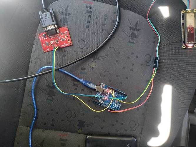
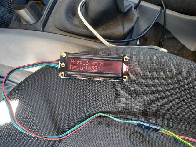 Arduino setup with OBD2 UART and LCD
7. Advanced Techniques For CAN Bus Integration
Once you’ve mastered the basics, you can explore more advanced techniques.
- Reading VIN (Vehicle Identification Number): The VIN can be retrieved using PID
0902. - Reading Diagnostic Trouble Codes (DTCs): DTCs provide valuable information about vehicle problems. Use PID
03to read stored DTCs. - Clearing DTCs: DTCs can be cleared using the
04PID. - Using CAN Bus Libraries: Consider using CAN bus libraries for Arduino, which can simplify the process of sending and receiving CAN bus messages.
8. Choosing The Right OBD2 PIDs
Selecting the correct OBD2 PIDs is vital for accessing the data you need. Here’s a list of common PIDs.
| PID | Description | Data Type | Units |
|---|---|---|---|
| 0100 | Supported PIDs [01-20] | Bitfield | – |
| 010C | Engine RPM | Integer | RPM |
| 010D | Vehicle Speed | Integer | km/h |
| 010E | Timing Advance | Integer | Degrees |
| 010F | Intake Air Temperature | Integer | Celsius |
| 0110 | Mass Air Flow Rate | Integer | g/s |
| 0111 | Throttle Position | Integer | Percent |
| 011C | OBD Standards | Integer | – |
| 011F | Run Time Since Engine Start | Integer | Seconds |
| 03 | Trouble Codes | String (multiple) | – |
Note: Not all vehicles support all PIDs. Consult your vehicle’s service manual for a complete list of supported PIDs.
9. Integrating With Other Sensors And Systems
The possibilities are endless when you start integrating CAN bus data with other sensors and systems.
- GPS Integration: Combine vehicle speed and location data for tracking and navigation.
- Accelerometer Integration: Monitor vehicle acceleration and braking forces.
- Data Logging to SD Card: Log vehicle data for later analysis.
- Wireless Communication: Send vehicle data to a remote server via Bluetooth or WiFi.
10. Case Studies: Real-World Applications
Here are a few examples of how CAN bus data can be used in real-world applications.
- DIY Heads-Up Display (HUD): Display vehicle speed, RPM, and other vital information on your windshield.
- Performance Monitoring System: Track engine performance and identify potential issues early.
- Fuel Efficiency Monitor: Monitor fuel consumption and optimize driving habits.
- Theft Prevention System: Use GPS and accelerometer data to detect and track vehicle theft.
11. Safety Considerations When Working With OBD2
Working with your vehicle’s OBD2 port involves certain safety considerations.
- Do Not Tamper While Driving: Only connect and disconnect devices when the vehicle is stationary and the engine is off.
- Avoid Data Overload: Requesting too much data can overwhelm the CAN bus and cause issues.
- Use Reliable Hardware: Use high-quality components to avoid damaging your vehicle’s electrical system.
- Consult Vehicle Manual: Refer to your vehicle’s service manual for specific information about the OBD2 port and CAN bus.
12. Alternatives To Sparkfun OBD2 UART
While the Sparkfun OBD2 UART is a popular choice, there are alternatives available.
- Seeed Studio CAN-BUS Shield: A shield that plugs directly into your Arduino.
- CANDIY Board: An open-source CAN bus interface.
- OBDLink MX+: A professional-grade OBD2 scanner that can also be used for DIY projects.
13. Understanding OBD2 Protocols
OBD2 protocols define the communication standards used by vehicles. Understanding these protocols is important for ensuring compatibility.
- SAE J1850 PWM: Used by Ford vehicles.
- SAE J1850 VPW: Used by GM vehicles.
- ISO 9141-2: Used by European and Asian vehicles.
- ISO 14230-4 (KWP2000): Used by many modern vehicles.
- ISO 15765-4 (CAN): The most common protocol used by modern vehicles.
14. Data Interpretation And Units
Interpreting the data received from the OBD2 port requires understanding the units and scaling factors.
- Speed: Kilometers per hour (km/h) or miles per hour (mph).
- RPM: Revolutions per minute.
- Temperature: Degrees Celsius or Fahrenheit.
- Pressure: Kilopascals (kPa) or pounds per square inch (psi).
15. Power Consumption And Management
Managing power consumption is important, especially in battery-powered applications.
- Use Low-Power Components: Choose Arduino boards and sensors with low power consumption.
- Implement Sleep Modes: Put the Arduino to sleep when it’s not actively collecting data.
- Optimize Code: Write efficient code to minimize processing time.
16. Legal And Ethical Considerations
Before embarking on your CAN bus project, consider the legal and ethical implications.
- Warranty Issues: Modifying your vehicle’s electronics may void the warranty.
- Data Privacy: Be mindful of the data you’re collecting and how you’re using it.
- Safety Regulations: Ensure your project complies with all applicable safety regulations.
17. The Future Of CAN Bus And Arduino
The future of CAN bus and Arduino is bright, with new applications and technologies emerging all the time.
- Connected Cars: CAN bus data will play an increasingly important role in connected car technologies.
- Autonomous Vehicles: Autonomous vehicles rely heavily on CAN bus data for navigation and control.
- AI Integration: AI algorithms can be used to analyze CAN bus data and improve vehicle performance.
18. Resources For Further Learning
Here are some valuable resources for expanding your knowledge of CAN bus and Arduino.
- Sparkfun OBD2 UART Hookup Guide: https://learn.sparkfun.com/tutorials/obd-ii-uart-hookup-guide
- Arduino CAN Bus Libraries: Search the Arduino library manager for CAN bus libraries.
- OBD2 PID Lists: Online databases of OBD2 PIDs.
- Automotive Forums: Online forums where you can ask questions and share your experiences.
19. Frequently Asked Questions (FAQ)
19.1. What is an OBD2 scanner?
An OBD2 scanner is a device used to read diagnostic trouble codes (DTCs) from a vehicle’s On-Board Diagnostic system.
19.2. How do I read OBD2 fault codes?
You can read OBD2 fault codes using an OBD2 scanner. Connect the scanner to the OBD2 port, turn on the ignition, and follow the scanner’s instructions to retrieve the codes.
19.3. What are common car errors and how can they be fixed?
Common car errors include engine misfires, oxygen sensor failures, and catalytic converter problems. These can often be diagnosed and fixed by a qualified mechanic using the information from an OBD2 scanner.
19.4. Can I use any Arduino board with the Sparkfun OBD2 UART?
Yes, most Arduino boards (Uno, Nano, Mega) are compatible with the Sparkfun OBD2 UART.
19.5. What baud rate should I use for serial communication?
The default baud rate for the Sparkfun OBD2 UART is 9600.
19.6. How do I know if my vehicle supports a specific PID?
You can try sending the PID and see if you receive a response. Alternatively, consult your vehicle’s service manual or an online OBD2 PID database.
19.7. What does a “NO DATA” response mean?
A “NO DATA” response indicates that the vehicle does not support the requested PID or that there is a communication problem.
19.8. Can I damage my vehicle by using an OBD2 scanner?
Using a quality OBD2 scanner correctly is unlikely to damage your vehicle. However, avoid using cheap or poorly designed scanners.
19.9. Where is the OBD2 port located in my car?
The OBD2 port is typically located under the dashboard on the driver’s side.
19.10. How can I clear the check engine light?
You can clear the check engine light by clearing the DTCs using an OBD2 scanner. However, the light will reappear if the underlying problem is not fixed.
 Close-up of an OBD2 port in a vehicle
20. Connect With OBD2-SCANNER.EDU.VN For Expert Assistance
Still facing challenges connecting your CAN bus to Arduino? Need expert guidance on interpreting OBD2 data or troubleshooting vehicle issues? Contact OBD2-SCANNER.EDU.VN today for personalized support and solutions!
Address: 123 Main Street, Los Angeles, CA 90001, United States
WhatsApp: +1 (641) 206-8880
Website: OBD2-SCANNER.EDU.VN
Let OBD2-SCANNER.EDU.VN help you unlock the full potential of your vehicle’s data and transform your automotive projects!