The 16 Pin Obd2 Pinout is your gateway to understanding your vehicle’s health. This standardized connector allows technicians and DIY enthusiasts to access diagnostic trouble codes (DTCs) and real-time data, providing valuable insights into your car’s performance. At OBD2-SCANNER.EDU.VN, we’re dedicated to helping you navigate the complexities of OBD2 technology. By understanding the OBD2 connector, you can troubleshoot issues faster and keep your vehicle running smoothly. Discover the world of automotive diagnostics with us and learn how to interpret vehicle data, use diagnostic tools, and perform vehicle maintenance efficiently.
Contents
- 1. Understanding the Basics of OBD2
- 1.1. How OBD2 Works
- 1.2. The Role of the Malfunction Indicator Light (MIL)
- 2. Is Your Car OBD2 Compliant?
- 2.1. OBD2 Compliance History
- 2.2. The Future of OBD2: OBD3 and Beyond
- 3. Decoding the OBD2 Connector
- 3.1. Type A vs. Type B Connectors
- 3.2. Common Issues and Troubleshooting
- 4. The OBD2 Protocol and CAN Bus
- 4.1. CAN Identifiers: 11-bit vs. 29-bit
- 4.2. OBD2 vs. Proprietary CAN Protocols
- 5. Understanding OBD2 Standards
- 5.1. ISO 15765: Diagnostics on CAN
- 5.2. SAE J1979 and ISO 15031-5: Diagnostic Services
- 6. Decoding OBD2 Messages
- 6.1. OBD2 Modes and Services
- 6.2. Parameter IDs (PIDs) Explained
- 7. Logging and Decoding OBD2 Data: A Practical Guide
- 7.1. Testing Bit-Rate, IDs, and Supported PIDs
- 7.2. Configuring PID Requests for Efficient Logging
- 8. Multi-Frame Communication in OBD2
- 8.1. Requesting the Vehicle Identification Number (VIN)
- 8.2. Understanding Diagnostic Trouble Codes (DTCs)
- 9. Real-World Applications of OBD2 Data Logging
- 9.1. Optimizing Driving Habits
- 9.2. Predictive Maintenance Strategies
1. Understanding the Basics of OBD2
What exactly is OBD2 and why is it so important for modern vehicles?
OBD2, or On-Board Diagnostics II, is a standardized system that allows you to monitor your vehicle’s performance and diagnose issues. According to a study by the SAE International, the OBD2 standard was developed to provide access to vehicle health information for emissions control and diagnostics. Think of it as your car’s built-in self-diagnostic system. Whenever that pesky malfunction indicator light (MIL), also known as the “check engine light,” illuminates on your dashboard, OBD2 is the technology that helps you figure out why. When you take your car to a mechanic, they use an OBD2 scanner to connect to your car’s computer via the 16-pin OBD2 connector, typically located near the steering wheel. This tool sends requests to the car, and the car responds with data like speed, fuel level, and those all-important Diagnostic Trouble Codes (DTCs). This capability enables technicians to quickly identify and resolve problems, ensuring your vehicle runs efficiently and safely.
1.1. How OBD2 Works
How does OBD2 collect and transmit all that crucial vehicle data?
The OBD2 system works by monitoring various sensors and components throughout your vehicle. These sensors continuously collect data related to engine performance, emissions, and other critical systems. When a sensor detects a problem or a reading that falls outside the specified parameters, it triggers a Diagnostic Trouble Code (DTC). This DTC is stored in the vehicle’s computer and can be accessed using an OBD2 scanner. The scanner sends a request for this information, and the vehicle responds by transmitting the DTC and other relevant data. According to research from the University of California, the standardized nature of OBD2 allows for consistent diagnostic procedures across different vehicle makes and models.
1.2. The Role of the Malfunction Indicator Light (MIL)
What does that illuminated “check engine light” really signify, and why should you care?
The Malfunction Indicator Light (MIL), often referred to as the “check engine light,” is your vehicle’s way of alerting you to a potential issue. When the MIL illuminates, it means that the OBD2 system has detected a problem that could affect your vehicle’s performance or emissions. It’s crucial not to ignore this warning. While the issue might be minor, such as a loose gas cap, it could also indicate a more serious problem, like a faulty oxygen sensor or a catalytic converter issue. Addressing the problem promptly can prevent further damage and costly repairs. At OBD2-SCANNER.EDU.VN, we advise you to use an OBD2 scanner to read the DTCs and understand the nature of the problem. This proactive approach can save you time and money in the long run, ensuring your vehicle remains in optimal condition.
2. Is Your Car OBD2 Compliant?
How can you determine if your car supports OBD2, and what are the key compliance milestones?
Determining whether your car is OBD2 compliant is usually straightforward. Most newer non-electric cars support OBD2 and often run on CAN bus. However, even if an older car has a 16-pin OBD2 connector, it may not fully support the OBD2 protocol. The easiest way to check compliance is by considering where and when the vehicle was bought new.
Generally, here’s a breakdown:
- 1996 and newer (USA): OBD2 is mandatory for all cars and light trucks sold in the United States.
- 2001 and newer (Europe – Gasoline): Required for gasoline cars in the European Union.
- 2004 and newer (Europe – Diesel): Required for diesel cars in the European Union (EOBD).
If your vehicle falls within these guidelines, it’s highly likely to be OBD2 compliant. If you’re unsure, you can consult your vehicle’s owner’s manual or contact a local mechanic. Understanding your vehicle’s compliance ensures you can effectively use OBD2 scanners for diagnostics and maintenance.
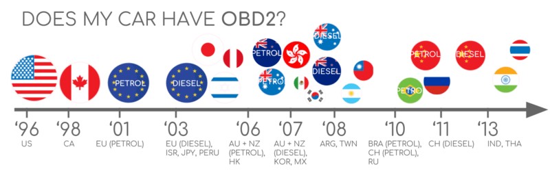
 Does My Car Have OBD2?
2.1. OBD2 Compliance History
What were the key milestones in the rollout of the OBD2 standard, and how did it evolve?
The history of OBD2 compliance is rooted in the need for better emissions control and diagnostic capabilities. It began in California, where the California Air Resources Board (CARB) mandated OBD in all new cars from 1991 onward for emissions control purposes. The Society of Automotive Engineers (SAE) recommended the OBD2 standard, standardizing DTCs and the OBD connector across manufacturers with SAE J1962.
Here’s a step-by-step overview of the OBD2 rollout:
- 1996: OBD2 became mandatory in the USA for cars and light trucks.
- 2001: The European Union required OBD for gasoline cars.
- 2003: The EU extended the requirement to include diesel cars (EOBD).
- 2005: OBD2 was required in the US for medium-duty vehicles.
- 2008: US cars were mandated to use ISO 15765-4 (CAN) as the OBD2 basis.
- 2010: OBD2 became required in US heavy-duty vehicles.
This gradual implementation has made OBD2 a ubiquitous standard in the automotive industry.
2.2. The Future of OBD2: OBD3 and Beyond
How is OBD2 evolving to meet the demands of modern connected cars, and what new features can we expect?
The future of OBD2 is moving towards more advanced and integrated systems like OBD3, which seeks to add telematics to all cars. Instead of manual emission control checks, OBD3 would use a small radio transponder in cars to send the Vehicle Identification Number (VIN) and DTCs via WiFi to a central server for checks. This advancement saves costs and increases convenience, although it raises some privacy concerns.
Modern alternatives like WWH-OBD (World Wide Harmonized OBD) and OBDonUDS (OBD on UDS) are also emerging. These aim to enhance OBD communication by leveraging the UDS protocol, offering streamlined and improved diagnostic capabilities.
However, there’s also a trend where manufacturers may restrict third-party access to OBD2 data, collecting data in a central server instead. This approach raises debates about data control and the future of third-party OBD2 services. Despite these potential changes, OBD2 remains a crucial technology for vehicle diagnostics and maintenance.
3. Decoding the OBD2 Connector
What is the purpose of each pin in the OBD2 connector, and how does it facilitate communication with the vehicle?
The OBD2 connector, defined by SAE J1962, is a 16-pin interface that provides access to your car’s data. Each pin serves a specific function, enabling communication between the diagnostic tool and the vehicle’s computer. Understanding the function of each pin is essential for effective diagnostics and troubleshooting. The connector is typically located near the steering wheel, though it may be hidden behind a panel.
Here’s a detailed breakdown of common pin assignments:
| Pin Number | Function | Common Usage |
|---|---|---|
| 2 | SAE J1850 Bus Positive | Used in older GM vehicles |
| 4 | Chassis Ground | Provides a ground connection for the diagnostic tool |
| 5 | Signal Ground | Provides a signal ground for the diagnostic tool |
| 6 | CAN High (J-2284) | Used for CAN bus communication, which is standard in most modern vehicles |
| 7 | ISO 9141-2 K Line | Used for ISO 9141-2 and KWP2000 communication protocols |
| 10 | SAE J1850 Bus Negative | Used in older Ford vehicles |
| 14 | CAN Low (J-2284) | Used for CAN bus communication, complementing pin 6 |
| 15 | ISO 9141-2 L Line | Used for ISO 9141-2 communication protocol |
| 16 | Battery Power | Supplies battery power to the diagnostic tool, even when the ignition is off |
| 1, 3, 8, 9, 11, 12, 13 | Manufacturer Discretion | Varies depending on the manufacturer; may be used for OEM-specific functions or diagnostics |
The OBD2 pinout depends on the communication protocol used by the vehicle. The most common lower-layer protocol is CAN bus, meaning that pins 6 (CAN-H) and 14 (CAN-L) are typically connected. This standardized connector simplifies the process of accessing vehicle data, making it easier for technicians and enthusiasts to diagnose and resolve issues.
3.1. Type A vs. Type B Connectors
What are the differences between Type A and Type B OBD2 connectors, and how do you identify the correct one for your vehicle?
In practice, you may encounter both Type A and Type B OBD2 connectors. Type A is typically found in cars, while Type B is common in medium and heavy-duty vehicles. The key difference lies in their power supply outputs: Type A provides 12V, whereas Type B provides 24V. The baud rate may also differ, with cars typically using 500K while heavy-duty vehicles often use 250K (though some newer models support 500K).
To distinguish them physically, note that the Type B OBD2 connector has an interrupted groove in the middle. A Type B OBD2 adapter cable is compatible with both Type A and Type B sockets, but a Type A adapter will not fit into a Type B socket. Knowing the difference ensures you use the correct adapter for your vehicle, preventing potential damage and ensuring proper communication with the vehicle’s computer.
3.2. Common Issues and Troubleshooting
What are some common problems encountered with OBD2 connectors, and how can you troubleshoot them effectively?
Several common issues can arise with OBD2 connectors, preventing proper communication between the scanner and the vehicle:
-
Damaged Pins: Physical damage to the pins is a frequent issue. Bent or broken pins can disrupt the connection. Inspect the connector carefully and straighten any bent pins with a small tool. Replace the connector if pins are broken.
-
Corrosion: Corrosion can build up on the pins, especially in older vehicles or those exposed to moisture. Use a contact cleaner specifically designed for electronics to remove corrosion and improve conductivity.
-
Loose Connection: A loose connection can occur if the connector isn’t fully seated or if the connector receptacle in the vehicle is worn. Ensure the connector is firmly plugged in. If the receptacle is loose, it may need to be tightened or replaced.
-
Wiring Issues: Problems with the wiring connected to the OBD2 connector can also cause communication failures. Check the wires for any signs of damage, such as cuts or fraying. Repair or replace any damaged wiring.
-
Scanner Compatibility: Sometimes, the issue may be with the scanner itself. Ensure your scanner is compatible with your vehicle’s make and model. Some scanners may require software updates to function correctly.
-
Blown Fuse: The OBD2 port is often protected by a fuse. If the port isn’t working, check the vehicle’s fuse box for a blown fuse related to the OBD2 system. Replace the fuse if necessary.
Addressing these issues promptly can help ensure reliable communication with your vehicle’s computer, allowing you to diagnose and resolve problems efficiently. If you are still facing issue, contact OBD2-SCANNER.EDU.VN for immediate support via Whatsapp at +1 (641) 206-8880, our experts are on standby to assist you.
4. The OBD2 Protocol and CAN Bus
How does OBD2 utilize the CAN bus protocol for communication, and what are the key specifications of this integration?
Since 2008, CAN bus has been the mandatory lower-layer protocol for OBD2 in all cars sold in the US, as specified by ISO 15765. ISO 15765-4, also known as Diagnostics over CAN or DoCAN, outlines specific restrictions applied to the CAN standard (ISO 11898). This integration standardizes the CAN interface for test equipment, focusing on the physical, data link, and network layers:
- The CAN bus bit-rate must be either 250K or 500K.
- The CAN IDs can be 11-bit or 29-bit.
- Specific CAN IDs are used for OBD requests and responses.
- The diagnostic CAN frame data length must be 8 bytes.
- The OBD2 adapter cable must be a maximum of 5 meters.
These specifications ensure consistent and reliable communication between diagnostic tools and the vehicle’s electronic control units (ECUs).
4.1. CAN Identifiers: 11-bit vs. 29-bit
What are the differences between 11-bit and 29-bit CAN identifiers in OBD2 communication, and how do they impact data transmission?
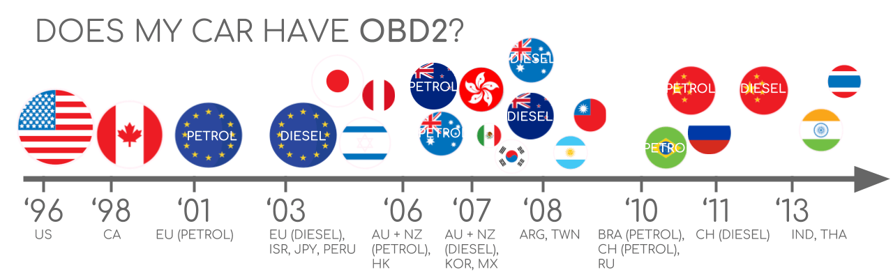
In OBD2 communication, both 11-bit and 29-bit CAN identifiers are used for request and response messages. Most cars use 11-bit CAN IDs, where the ‘Functional Addressing’ ID is 0x7DF. This ID asks all OBD2-compatible ECUs if they have data to report on the requested parameter. CAN IDs 0x7E0-0x7E7 can be used for ‘Physical Addressing’ requests from specific ECUs, though this is less common. ECUs respond with 11-bit IDs ranging from 0x7E8 to 0x7EF, with 0x7E8 (ECM, Engine Control Module) being the most common.
In some vehicles, particularly vans and light/medium/heavy-duty vehicles, extended 29-bit CAN identifiers are used. Here, the ‘Functional Addressing’ CAN ID is 0x18DB33F1. Responses are seen with CAN IDs ranging from 0x18DAF100 to 0x18DAF1FF. The response ID is sometimes shown in the J1939 PGN form, specifically PGN 0xDA00 (55808), which is marked as ‘Reserved for ISO 15765-2’ in the J1939-71 standard. Understanding these identifiers is crucial for interpreting CAN bus traffic and diagnosing vehicle issues.
 OBD2 OBD CAN bus Identifiers 7DF 7E8 7E0
4.2. OBD2 vs. Proprietary CAN Protocols
How does OBD2 communication differ from proprietary CAN protocols used by vehicle manufacturers, and why is this distinction important?
Your car’s electronic control units (ECUs) do not rely on OBD2 to function. Instead, each original equipment manufacturer (OEM) implements its own proprietary CAN protocols. These CAN protocols are specific to the vehicle’s brand, model, and year. Unless you are the OEM or can reverse engineer the data, you typically cannot interpret this data.
When you connect a CAN bus data logger to your car’s OBD2 connector, you might see the OEM-specific CAN data, often broadcast at a high rate. However, many newer cars use a ‘gateway’ that blocks access to this CAN data, only allowing OBD2 communication via the OBD2 connector.
Think of OBD2 as an ‘extra’ higher-layer protocol running in parallel to the OEM-specific protocol. While OBD2 provides standardized diagnostic information, the proprietary protocols control the vehicle’s core functions. This distinction is crucial for understanding the scope and limitations of OBD2 data when diagnosing and monitoring vehicle performance.
5. Understanding OBD2 Standards
What are the key standards that govern OBD2, and how do they ensure compatibility and consistency across different vehicles?
On-board diagnostics (OBD2) is a higher-layer protocol, much like a language, while CAN is a method for communication, akin to a phone. This makes OBD2 comparable to other CAN-based higher-layer protocols like J1939, CANopen, and NMEA 2000. The OBD2 standards specify the OBD2 connector, lower-layer protocols, and OBD2 parameter IDs (PIDs).
The standards can be organized in a 7-layer OSI model:
| Layer | Standard Examples | Description |
|---|---|---|
| Application | SAE J1979, ISO 15031-5 | Defines diagnostic services, DTCs, and PIDs |
| Presentation | ISO 15765-2 | Specifies data encoding and formatting |
| Session | ISO 15765-3 | Manages communication sessions |
| Transport | ISO 15765-2 | Handles message segmentation and reassembly |
| Network | ISO 15765-4 | Defines addressing and routing |
| Data Link | ISO 11898 | Manages data transfer between nodes |
| Physical | SAE J1962, ISO 15031-3, ISO 11898 | Specifies the physical connector and electrical characteristics of the bus |
Several layers are covered by both SAE and ISO standards, reflecting standards defined in the USA (SAE) and the EU (ISO). Many standards are technically equivalent, such as SAE J1979 vs. ISO 15031-5 and SAE J1962 vs. ISO 15031-3. These standards ensure compatibility and consistency in OBD2 communication across different vehicle makes and models.
5.1. ISO 15765: Diagnostics on CAN
What does the ISO 15765 standard specify for OBD2 communication over CAN, and why is it crucial for modern vehicles?
ISO 15765, particularly ISO 15765-4 (Diagnostics over CAN or DoCAN), specifies how OBD2 communication is conducted over the CAN bus. It applies restrictions to the CAN standard (ISO 11898) to standardize the interface for test equipment. This includes defining the CAN bus bit-rate (250K or 500K), CAN ID lengths (11-bit or 29-bit), specific CAN IDs for OBD requests/responses, a diagnostic CAN frame data length of 8 bytes, and a maximum OBD2 adapter cable length of 5 meters. According to SAE International, ISO 15765 ensures that all OBD2-compliant vehicles use a consistent communication protocol, allowing any standard OBD2 scanner to retrieve diagnostic information. This standardization is crucial for enabling accurate and reliable vehicle diagnostics.
5.2. SAE J1979 and ISO 15031-5: Diagnostic Services
What do SAE J1979 and ISO 15031-5 define regarding OBD2 diagnostic services, and how do they facilitate retrieving vehicle data?
SAE J1979 and ISO 15031-5 define the diagnostic services (or modes) that OBD2 scanners use to retrieve data from vehicles. These standards specify the format and content of request and response messages, including parameter IDs (PIDs) and Diagnostic Trouble Codes (DTCs). There are 10 standardized OBD2 diagnostic services, with mode 0x01 providing current real-time data and others used to show or clear DTCs or display freeze-frame data.
Vehicles do not have to support all OBD2 modes and may include OEM-specific modes outside the 10 standardized ones. In OBD2 messages, the mode is in the second byte. In the request, the mode is included directly (e.g., 0x01), while in the response, 0x40 is added to the mode (e.g., resulting in 0x41). The standards ensure that diagnostic tools can reliably access and interpret vehicle data, making troubleshooting and maintenance more efficient.
6. Decoding OBD2 Messages
How are OBD2 messages structured, and what are the key components that carry diagnostic information?
To understand OBD2 on CAN, consider a raw ‘Single Frame’ OBD2 CAN message. In simple terms, an OBD2 message includes an identifier, data length (PCI field), and data. The data is divided into Mode, parameter ID (PID), and data bytes. The OBD2 diagnostic message is based on SAE J1979 and ISO 15031-5.
Here’s a breakdown of the structure:
- Identifier: The CAN ID used for communication (e.g., 0x7DF for requests, 0x7E8 for responses).
- Data Length (PCI Field): Indicates the length of the data payload.
- Mode: Specifies the diagnostic service being requested (e.g., 0x01 for real-time data).
- Parameter ID (PID): Identifies the specific parameter being requested (e.g., 0x0D for vehicle speed).
- Data Bytes: Contain the actual data values for the requested parameter.
6.1. OBD2 Modes and Services
What are the different OBD2 modes or services, and how are they used for various diagnostic functions?
There are 10 OBD2 diagnostic services (or modes) defined in the standards. Each mode serves a specific purpose in accessing and managing vehicle diagnostic information:
| Mode (Hex) | Description | Usage |
|---|---|---|
| 0x01 | Show current data | Displays real-time data, such as speed, RPM, and temperature. |
| 0x02 | Show freeze frame data | Shows data captured when a DTC was set. |
| 0x03 | Show stored Diagnostic Trouble Codes (DTCs) | Displays current DTCs stored in the vehicle’s computer. |
| 0x04 | Clear Diagnostic Trouble Codes (DTCs) and reset emission-related diagnostics | Clears DTCs and resets emission-related diagnostic information. |
| 0x05 | Oxygen sensor monitoring test results | Displays results from oxygen sensor monitoring tests. |
| 0x06 | Non-continuously monitored systems test results | Shows test results for systems that are not continuously monitored. |
| 0x07 | Show pending DTCs | Displays DTCs that have been detected but not yet confirmed. |
| 0x08 | Control operation of on-board system, test or component | Allows control and testing of specific on-board systems. |
| 0x09 | Request vehicle information | Requests vehicle information, such as VIN and calibration IDs. |
| 0x0A | Show permanent DTCs | Displays DTCs that cannot be cleared by normal means. |
Vehicles do not have to support all OBD2 modes and may support OEM-specific modes. In OBD2 messages, the mode is in the 2nd byte. In the request, the mode is included directly (e.g., 0x01), while in the response, 0x40 is added to the mode (resulting in 0x41).
6.2. Parameter IDs (PIDs) Explained
What are OBD2 parameter IDs (PIDs), and how do they help in accessing specific data points from the vehicle’s computer?
Each OBD2 mode contains parameter IDs (PIDs). For example, mode 0x01 contains approximately 200 standardized PIDs with real-time data on parameters like speed, RPM, and fuel level. However, a vehicle does not have to support all OBD2 PIDs in a mode. In practice, most vehicles support only a small subset.
If an emissions-related ECU supports any OBD2 services, it must support mode 0x01 PID 0x00. This PID is used to determine whether the vehicle ECU supports PIDs 0x01-0x20. PIDs 0x20, 0x40, …, 0xC0 can be used to determine support for the remaining mode 0x01 PIDs. PIDs enable you to request specific data points from the vehicle’s computer, making diagnostics more targeted and efficient.
7. Logging and Decoding OBD2 Data: A Practical Guide
How can you log and decode OBD2 data effectively, and what tools and techniques are involved?
To log and decode OBD2 data, you need a CAN bus data logger and appropriate software. One such tool is the CANedge, which allows you to configure custom CAN frames for transmitting OBD2 requests.
Here’s a step-by-step guide:
-
Test Bit-Rate, IDs, and Supported PIDs: Use ISO 15765-4 to determine the bit-rate and IDs used by the vehicle. Send CAN frames at 500K and check if successful (if not, try 250K). Send multiple ‘Supported PIDs’ requests and review the responses to determine 11-bit vs. 29-bit IDs and identify supported PIDs.
-
Configure OBD2 PID Requests: Set up a transmit list with the PIDs you want to monitor. Use ‘Physical Addressing’ request IDs (e.g., 0x7E0) to avoid multiple responses. Add spacing (300-500 ms) between requests to prevent ECU overload.
-
DBC Decode Raw OBD2 Data: Decode the raw OBD2 data into physical values using the decoding information in ISO 15031-5/SAE J1979. Use an OBD2 DBC file to simplify the process in CAN bus software tools.
7.1. Testing Bit-Rate, IDs, and Supported PIDs
Why is it essential to test the bit-rate, IDs, and supported PIDs before logging OBD2 data, and how can you do it effectively?
Testing the bit-rate, IDs, and supported PIDs is essential because it ensures you are communicating with the vehicle correctly. ISO 15765-4 provides a systematic way to determine these parameters:
-
Bit-Rate: Start by sending a CAN frame at 500K. If successful, use this bit-rate for subsequent communication. If not, try 250K.
-
CAN IDs: Based on the response IDs, you can determine whether the vehicle uses 11-bit or 29-bit CAN IDs.
-
Supported PIDs: Send multiple ‘Supported PIDs’ requests (Mode 0x01 PID 0x00) and review the responses. The response data will indicate which PIDs are supported by the vehicle.
Most 2008+ non-EV cars support 40-80 PIDs via a 500K bit-rate, 11-bit CAN IDs, and the OBD2/OBDonEDS protocol. This validation process ensures that you only request data that the vehicle can provide, optimizing the logging process and preventing errors.
7.2. Configuring PID Requests for Efficient Logging
What factors should you consider when configuring OBD2 PID requests for efficient data logging?
When configuring OBD2 PID requests, consider these factors for efficient data logging:
- CAN IDs: Use ‘Physical Addressing’ request IDs (e.g., 0x7E0) to avoid multiple responses and reduce bus load.
- Spacing: Add 300-500 ms between each OBD2 request. Spamming the ECUs can cause them to stop responding.
- Battery Drain: Use triggers to stop transmitting when the vehicle is inactive, preventing unnecessary battery drain.
- Filters: Add filters to record only OBD2 responses, especially if your vehicle also outputs OEM-specific CAN data.
By optimizing these settings, you can ensure reliable and efficient OBD2 data logging, capturing the data you need without overloading the vehicle’s communication bus or draining the battery.
8. Multi-Frame Communication in OBD2
When is multi-frame communication necessary in OBD2, and how does it work?
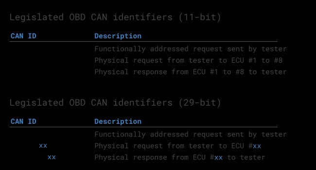
Multi-frame communication in OBD2 is necessary when the data being transmitted exceeds the 8-byte limit of a single CAN frame. This often occurs when requesting the Vehicle Identification Number (VIN) or Diagnostic Trouble Codes (DTCs). ISO 15765-2 (ISO-TP) handles this by segmenting the data, managing flow control, and reassembling the message.
Multi-frame communication requires flow control frames. A common practice is to transmit a static flow control frame approximately 50 ms after the initial request frame. CAN software and API tools that support ISO-TP, like the CANedge MF4 decoders, are needed to handle multi-frame OBD2 responses.
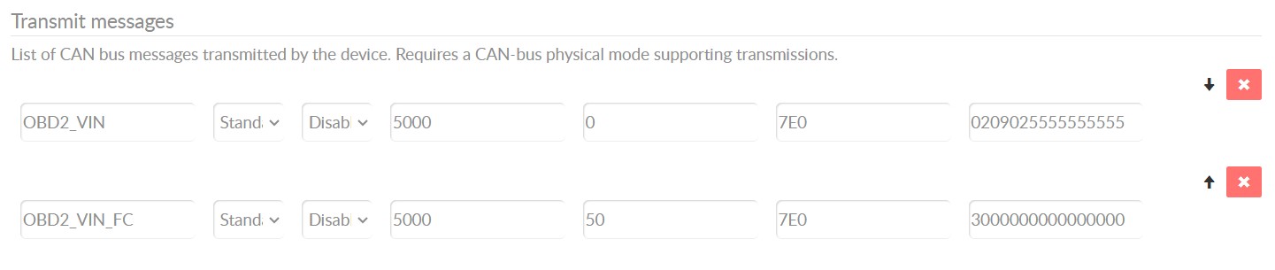 OBD2-multi-frame-request-message-vehicle-identification-number
8.1. Requesting the Vehicle Identification Number (VIN)
How do you use OBD2 to request the Vehicle Identification Number (VIN) and what does the multi-frame communication process look like?
To extract the VIN from a vehicle using OBD2 requests, you use mode 0x09 and PID 0x02. The process involves multi-frame communication due to the VIN’s length:
- The tester tool sends a Single Frame request with the PCI field (0x02), request service identifier (0x09), and PID (0x02).
- The vehicle responds with a First Frame containing the PCI, length (0x014 = 20 bytes), mode (0x49, i.e., 0x09 + 0x40), and PID (0x02).
- Following the PID is the byte 0x01, representing the Number Of Data Items (NODI), in this case, 1.
- The remaining 17 bytes equal the VIN, which can be translated from HEX to ASC.
This multi-frame process ensures that the entire VIN is transmitted, despite exceeding the single-frame data limit.
8.2. Understanding Diagnostic Trouble Codes (DTCs)
How can you use OBD2 to retrieve Diagnostic Trouble Codes (DTCs), and what do these codes signify?
You can use OBD2 to request emissions-related Diagnostic Trouble Codes (DTCs) using mode 0x03, i.e., ‘Show stored Diagnostic Trouble Codes’. No PID is included in the request. The targeted ECU(s) will respond with the number of DTCs they have stored, with each DTC taking up 2 data bytes. Multi-frame responses are necessary when more than 2 DTCs are stored.
The 2-byte DTC value is split into two parts. The first 2 bits define the ‘category’, while the remaining 14 bits define a 4-digit code (displayed in hexadecimal). The decoded DTC values can be looked up in OBD2 DTC lookup tools like repairpal.com. For example, the illustration shows a request to an ECU with 6 DTCs stored.
Understanding DTCs is essential for diagnosing and resolving vehicle issues, as they provide specific information about the nature and location of the problem.
9. Real-World Applications of OBD2 Data Logging
What are some practical use cases for OBD2 data logging, and how can this data be leveraged to improve vehicle performance and maintenance?
OBD2 data logging has numerous real-world applications, including:
- Fuel Efficiency Improvement: Monitoring fuel consumption in real-time can help drivers adjust their driving habits to save fuel.
- Performance Tuning: Engine performance data can be used to fine-tune engine parameters for optimal power and efficiency.
- Predictive Maintenance: Tracking sensor data over time can help identify potential component failures before they occur, enabling proactive maintenance.
- Fleet Management: Logging data from multiple vehicles can provide insights into fleet performance, driver behavior, and maintenance needs.
- Accident Analysis: Data logged during or leading up to an accident can help reconstruct events and determine the cause.
These use cases demonstrate the versatility and value of OBD2 data logging in improving vehicle performance, safety, and maintenance practices.
9.1. Optimizing Driving Habits
How can OBD2 data help drivers optimize their driving habits for better fuel efficiency and vehicle longevity?
OBD2 data can provide valuable insights into driving habits, allowing drivers to make adjustments that improve fuel efficiency and extend vehicle life. By monitoring parameters such as speed, RPM, throttle position, and fuel consumption, drivers can identify inefficient behaviors like:
- Aggressive Acceleration: Rapid acceleration consumes more fuel. Smooth, gradual acceleration is more efficient.
- Hard Braking: Frequent hard braking indicates a lack of anticipation. Coasting and gentle braking save fuel and reduce wear on brake components.
- High RPMs: Driving at high RPMs increases fuel consumption and engine wear. Shifting gears at lower RPMs is more efficient.
- Idling: Excessive idling wastes fuel. Turning off the engine during long stops can save fuel.
By using OBD2 data to identify and correct these habits, drivers can significantly improve their fuel economy and reduce wear and tear on their vehicles.
9.2. Predictive Maintenance Strategies
How can OBD2 data be used to develop predictive maintenance strategies that minimize downtime and reduce repair costs?
OBD2 data enables predictive maintenance by providing real-time insights into the health and performance of various vehicle components. By continuously monitoring key parameters, potential issues can be identified before they lead to breakdowns. Some predictive maintenance strategies include: