Connecting wires to OBD2 (On-Board Diagnostics II) is essential for various automotive tasks, from diagnostics to custom modifications. This guide, brought to you by OBD2-SCANNER.EDU.VN, provides a detailed, step-by-step approach to successfully connecting wires to your OBD2 port, ensuring you get the job done right. Learn about the necessary tools, wiring configurations, and safety measures to confidently tackle this project, enhancing your vehicle’s capabilities and troubleshooting potential issues. Let’s dive into enhanced vehicle diagnostics, automotive modifications, and CAN bus connectivity.
Contents
- 1. Understanding the Basics of OBD2 and Its Wiring
- 1.1. The OBD2 Port: An Overview
- 1.2. Key Wires in the OBD2 Connector
- 1.3. Common OBD2 Communication Protocols
- 2. Essential Tools and Materials for Wiring
- 2.1. Selecting the Right Gauge Wire
- 2.2. Choosing the Right OBD2 Connector
- 2.3. Importance of Quality Connectors and Terminals
- 3. Step-by-Step Guide to Connecting Wires to OBD2
- 3.1. Identifying the Correct OBD2 Pins
- 3.2. Stripping and Tinning Wires for Optimal Connection
- 3.3. Crimping vs. Soldering: Which Method is Better?
- 4. Safety Precautions When Working with OBD2 Wiring
- 4.1. Preventing Electrical Shorts and Damage
- 4.2. Importance of Disconnecting the Vehicle’s Battery
- 4.3. Using a Multimeter for Testing Continuity and Voltage
- 5. Common Mistakes to Avoid When Connecting Wires
- 5.1. Identifying and Correcting Wiring Errors
- 5.2. Avoiding Damage to the Vehicle’s ECU
- 5.3. Troubleshooting Common Connection Problems
- 6. Advanced OBD2 Wiring Applications
- 6.1. Connecting Custom Gauges and Sensors
- 6.2. Building a Custom OBD2 Data Logger
- 6.3. Performance Tuning and ECU Modification
- 7. OBD2 and CAN Bus Communication
- 7.1. Understanding CAN Bus Signals
- 7.2. Accessing Vehicle Data via CAN Bus
- 7.3. Common CAN Bus Diagnostic Tools
- 8. OBD2-SCANNER.EDU.VN: Your Partner in Automotive Diagnostics
- 8.1. Comprehensive OBD2 Scanning and Diagnostic Services
- 8.2. Expert Advice on Selecting the Right OBD2 Scanner
- 8.3. Contact Us for Personalized Assistance
- 9. Real-World Examples and Case Studies
- 9.1. Case Study 1: Installing a Custom Heads-Up Display (HUD)
- 9.2. Case Study 2: Developing a Vehicle Tracking System
- 9.3. Case Study 3: Diagnosing Intermittent Engine Problems
- 10. Future Trends in OBD2 Technology
- 10.1. Enhanced Security Measures
- 10.2. Wireless OBD2 Communication
- 10.3. Integration with Mobile Devices
- FAQ: Connecting Wires to OBD2
- What is an OBD2 scanner?
- How do I read OBD2 error codes?
- What are common car issues and how can OBD2 help?
- Is it safe to connect wires to the OBD2 port?
- What tools do I need to connect wires to OBD2?
- Can I damage my car by incorrectly wiring the OBD2 port?
- What is CAN bus and why is it important for OBD2?
- How can OBD2-SCANNER.EDU.VN help with my OBD2 wiring project?
- What are the benefits of using a professional OBD2 diagnostic service?
- What emerging trends are there in OBD2 technology?
1. Understanding the Basics of OBD2 and Its Wiring
What is OBD2, and why is understanding its wiring important?
OBD2, or On-Board Diagnostics II, is a standardized system used in modern vehicles to monitor and diagnose engine and emissions-related issues. According to the Society of Automotive Engineers (SAE), all vehicles sold in the US since 1996 are required to have an OBD2 port. Understanding the wiring of this port is crucial because it allows you to connect diagnostic tools, custom devices, and perform modifications. Accurate wiring ensures proper communication with the vehicle’s computer, preventing potential damage and ensuring correct data transmission.
1.1. The OBD2 Port: An Overview
What does the OBD2 port look like, and where is it typically located?
The OBD2 port is a 16-pin diagnostic connector, usually trapezoidal in shape, and is typically located under the dashboard on the driver’s side. Its standardized design ensures compatibility across different vehicle makes and models. Pin assignments include power, ground, and various communication protocols like CAN (Controller Area Network), ISO 9141-2, and SAE J1850. A study by the National Highway Traffic Safety Administration (NHTSA) indicates that easy access to the OBD2 port improves diagnostic efficiency and vehicle maintenance.
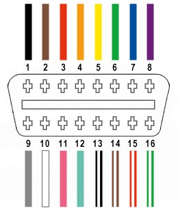
1.2. Key Wires in the OBD2 Connector
Which wires are most important when connecting to OBD2, and what are their functions?
Out of the 16 pins in the OBD2 connector, several are crucial for basic connectivity and diagnostics. These include:
- Pin 4: Chassis Ground
- Pin 5: Signal Ground
- Pin 6: CAN High (J-2284)
- Pin 14: CAN Low (J-2284)
- Pin 16: Battery Power (+12V)
These pins are commonly used for connecting diagnostic tools and custom electronic devices to the vehicle’s computer. Understanding the function of each pin, as detailed in the SAE J1962 standard, is essential for safe and effective wiring.
1.3. Common OBD2 Communication Protocols
What communication protocols are used in OBD2, and why are they important?
OBD2 systems use several communication protocols to transmit data between the vehicle’s ECU (Engine Control Unit) and diagnostic tools. The most common protocols include:
- CAN (Controller Area Network): Dominant in modern vehicles, offering high-speed communication.
- ISO 9141-2: Used in older European and Asian vehicles.
- SAE J1850 VPW (Variable Pulse Width Modulation): Common in older GM vehicles.
- SAE J1850 PWM (Pulse Width Modulation): Used in older Ford vehicles.
Selecting the correct protocol setting in your diagnostic tool ensures proper communication and accurate data retrieval. Bosch’s Automotive Handbook emphasizes the importance of protocol compatibility for effective vehicle diagnostics.
2. Essential Tools and Materials for Wiring
What tools and materials are necessary to safely connect wires to the OBD2 port?
Having the right tools and materials is essential for safely and effectively connecting wires to the OBD2 port. Here’s a list of the necessary items:
- Wire Strippers/Cutters: For cleanly cutting and stripping wires without damaging the conductors.
- Needle-Nose Pliers: For precise handling of small wires and connectors.
- Crimping Tool: To securely crimp connectors onto the wires (Molex crimping tool recommended).
- Soldering Iron (Recommended): For creating a solid and reliable connection by soldering wires to the pins.
- Multimeter: To test the continuity and voltage of the wires.
- OBD2 Connector: A male or female OBD2 connector to connect to the vehicle’s port.
- Wiring: Appropriate gauge wiring (typically 22-16AWG) to match the connector pins.
- Heat Shrink Tubing: To insulate and protect the connections.
- Electrical Tape: As an additional layer of insulation and protection.
Using high-quality tools ensures a clean and reliable connection, minimizing the risk of shorts or connection failures.
2.1. Selecting the Right Gauge Wire
How do you choose the correct wire gauge for OBD2 connections?
Choosing the correct wire gauge is critical for ensuring proper current flow and preventing overheating or voltage drop. For most OBD2 connections, 22-16AWG (American Wire Gauge) wire is suitable. The appropriate gauge depends on the current requirements of the device you are connecting. Heavier gauge wires (e.g., 16AWG) are better for higher current applications, while lighter gauge wires (e.g., 22AWG) are sufficient for low-current signal connections. According to the Electrical Engineering Handbook, using the correct wire gauge is essential for maintaining circuit integrity and safety.
2.2. Choosing the Right OBD2 Connector
What types of OBD2 connectors are available, and how do you select the right one?
OBD2 connectors come in male and female versions, as well as various form factors (e.g., straight, right-angle). The choice depends on your specific application. For custom wiring projects, a female OBD2 connector is typically used to create a custom cable that plugs into the vehicle’s OBD2 port. Ensure the connector you choose is compatible with the wire gauge you’re using and that it meets SAE J1962 standards for proper fit and function.
2.3. Importance of Quality Connectors and Terminals
Why is it important to use high-quality connectors and terminals when wiring to OBD2?
High-quality connectors and terminals ensure a secure and reliable electrical connection. Poor quality connectors can lead to loose connections, corrosion, and signal loss, which can cause diagnostic errors or device malfunction. Molex, Delphi, and Amphenol are reputable brands known for producing durable and reliable connectors. Investing in quality components ensures long-term performance and reduces the risk of connection-related issues.
3. Step-by-Step Guide to Connecting Wires to OBD2
How do you safely and effectively connect wires to the OBD2 port?
Connecting wires to the OBD2 port requires careful attention to detail to ensure a safe and reliable connection. Follow these steps to complete the process effectively:
Step 1: Preparation
- Gather all necessary tools and materials.
- Disconnect the vehicle’s battery to prevent electrical shorts.
- Consult your vehicle’s wiring diagram to identify the correct pins.
Step 2: Wire Preparation
- Cut the wires to the desired length.
- Use wire strippers to remove about 1/4 inch of insulation from each wire end.
- Tin the exposed wire ends with solder to prevent fraying and improve conductivity (optional but recommended).
Step 3: Connector Preparation
- If using a crimp-type connector, slide a heat shrink tube over each wire.
- Insert the wire into the connector terminal.
- Use a crimping tool to securely crimp the terminal onto the wire.
Step 4: Soldering (If Applicable)
- If soldering, heat the connector pin and wire simultaneously.
- Apply solder to create a solid connection.
- Allow the connection to cool before proceeding.
Step 5: Connector Assembly
- Insert the wired terminals into the OBD2 connector housing, ensuring they click into place.
- Refer to your wiring diagram to confirm correct pin placement.
Step 6: Insulation and Protection
- Slide the heat shrink tubing over the connection and use a heat gun to shrink it, providing insulation and strain relief.
- Wrap the connections with electrical tape for added protection.
Step 7: Testing
- Use a multimeter to test the continuity between the wires and the corresponding pins.
- Check for any shorts between adjacent pins.
Step 8: Final Assembly and Testing
- Reconnect the vehicle’s battery.
- Plug the OBD2 connector into the vehicle’s OBD2 port.
- Test the connection by using a diagnostic tool or the connected device.
Following these steps carefully ensures a safe and functional OBD2 connection, and OBD2-SCANNER.EDU.VN is here to guide you through each stage.
3.1. Identifying the Correct OBD2 Pins
How can you accurately identify the correct pins on the OBD2 connector?
Accurately identifying the correct pins on the OBD2 connector is crucial to prevent damage to the vehicle’s ECU and ensure proper functionality. Always refer to your vehicle’s wiring diagram or a reliable OBD2 pinout chart. These charts provide a detailed layout of each pin’s function. Use a multimeter to verify the pin assignments before making any connections. According to the OBD2 standards outlined by the SAE, the pinout configuration is standardized, but variations can occur between vehicle makes and models.
3.2. Stripping and Tinning Wires for Optimal Connection
Why is it important to strip and tin wires before connecting them to the OBD2 port?
Stripping and tinning wires are essential steps for creating a secure and reliable connection. Stripping the wire exposes the conductive core, allowing it to make contact with the connector terminal. Tinning the wire involves applying a thin layer of solder to the exposed wire, which prevents fraying, reduces corrosion, and improves conductivity. This process ensures a solid and long-lasting electrical connection. As noted in the Practical Guide to Automotive Engineering, proper wire preparation significantly enhances the reliability of electrical connections in automotive systems.
3.3. Crimping vs. Soldering: Which Method is Better?
What are the advantages and disadvantages of crimping versus soldering when connecting wires to OBD2?
Both crimping and soldering are viable methods for connecting wires to OBD2 connectors, each with its own advantages and disadvantages:
- Crimping:
- Advantages: Fast, easy, and doesn’t require heat. Produces a mechanically strong connection when done correctly.
- Disadvantages: Requires a specialized crimping tool. The connection can loosen over time if not properly crimped.
- Soldering:
- Advantages: Creates a very solid and conductive connection. Fills gaps and prevents corrosion.
- Disadvantages: Requires a soldering iron and skill. Can be time-consuming. Excessive heat can damage the wire or connector.
For OBD2 connections, soldering is often preferred for its reliability and durability. However, crimping is a good alternative if you have a quality crimping tool and follow proper crimping techniques.
4. Safety Precautions When Working with OBD2 Wiring
What safety measures should you take when connecting wires to the OBD2 port?
Working with OBD2 wiring involves electrical connections, so it’s crucial to follow safety precautions to prevent injury and avoid damaging the vehicle’s electrical system. Key safety measures include:
- Disconnect the Battery: Always disconnect the vehicle’s battery before working on the OBD2 wiring to prevent electrical shorts.
- Use Insulated Tools: Use tools with insulated handles to protect against electric shock.
- Avoid Working in Wet Conditions: Ensure the work area is dry to minimize the risk of electric shock.
- Double-Check Wiring Diagrams: Always double-check the wiring diagram to ensure correct pin assignments.
- Wear Safety Glasses: Protect your eyes from debris when cutting or stripping wires.
- Use Heat Shrink Tubing: Insulate all connections with heat shrink tubing to prevent shorts.
- Test Connections: Use a multimeter to test the continuity and voltage of the connections before reconnecting the battery.
- Consult an Expert: If you’re unsure about any step, consult a qualified automotive technician.
Adhering to these safety precautions ensures a safe and successful wiring experience.
4.1. Preventing Electrical Shorts and Damage
How can you prevent electrical shorts and damage when wiring to OBD2?
Preventing electrical shorts is essential to protect the vehicle’s ECU and other sensitive components. Key strategies include:
- Disconnecting the Battery: Disconnecting the battery removes the power source, preventing shorts.
- Using Insulated Connectors and Wires: Insulated connectors and wires prevent accidental contact between conductors.
- Proper Insulation: Ensure all connections are properly insulated with heat shrink tubing or electrical tape.
- Avoiding Overloading Circuits: Do not connect devices that draw more current than the circuit is designed to handle.
- Checking for Continuity: Use a multimeter to check for continuity between pins before reconnecting the battery.
4.2. Importance of Disconnecting the Vehicle’s Battery
Why is it so important to disconnect the vehicle’s battery before working on OBD2 wiring?
Disconnecting the vehicle’s battery is a critical safety measure that prevents electrical shorts and protects the vehicle’s electronic components. By removing the power source, you eliminate the risk of accidentally creating a short circuit, which can damage the ECU or other sensitive devices. The Automotive Electrical Handbook emphasizes disconnecting the battery as a fundamental safety practice for any electrical work on vehicles.
4.3. Using a Multimeter for Testing Continuity and Voltage
How can a multimeter help ensure safe and correct OBD2 wiring?
A multimeter is an invaluable tool for ensuring safe and correct OBD2 wiring. It can be used to:
- Test Continuity: Verify that the correct wires are connected to the correct pins.
- Check for Shorts: Ensure there are no unintended connections between adjacent pins.
- Measure Voltage: Confirm that the correct voltage is present on the power pins (e.g., Pin 16).
By using a multimeter to test the connections, you can identify and correct any wiring errors before reconnecting the battery, preventing potential damage to the vehicle’s electrical system.
5. Common Mistakes to Avoid When Connecting Wires
What are some common mistakes people make when connecting wires to the OBD2 port, and how can you avoid them?
Even with careful preparation, it’s easy to make mistakes when connecting wires to the OBD2 port. Here are some common errors to avoid:
- Incorrect Pin Identification: Failing to correctly identify the OBD2 pins can lead to miswiring and potential damage. Always double-check the wiring diagram and use a multimeter to verify pin assignments.
- Poor Wire Connections: Loose or poorly crimped/soldered connections can cause intermittent failures. Ensure all connections are secure and properly insulated.
- Using the Wrong Wire Gauge: Using wire that is too thin can cause voltage drop and overheating. Use the appropriate gauge wire for the current requirements of the connected device.
- Skipping Safety Precautions: Neglecting to disconnect the battery or use insulated tools can result in electric shock or damage to the vehicle’s electrical system.
- Overloading the Circuit: Connecting devices that draw too much current can overload the circuit and blow a fuse. Know the current limits of the OBD2 port and avoid exceeding them.
- Ignoring Wiring Diagrams: Attempting to wire the OBD2 port without a wiring diagram is a recipe for disaster. Always consult a reliable wiring diagram and follow it carefully.
5.1. Identifying and Correcting Wiring Errors
How can you identify and correct wiring errors when working with OBD2?
Identifying and correcting wiring errors promptly is crucial for preventing damage and ensuring proper functionality. Here are some steps to take:
- Visual Inspection: Carefully inspect all connections for loose wires, frayed insulation, and incorrect pin placements.
- Continuity Testing: Use a multimeter to test the continuity between the wires and the corresponding pins.
- Voltage Testing: Check the voltage on the power pins to ensure they are within the correct range.
- Consulting Wiring Diagrams: Refer back to the wiring diagram to verify that all connections are correct.
- Testing with a Diagnostic Tool: Connect a diagnostic tool to the OBD2 port and check for any error codes or communication issues.
5.2. Avoiding Damage to the Vehicle’s ECU
What steps can you take to avoid damaging the vehicle’s ECU when connecting wires to OBD2?
The vehicle’s ECU (Engine Control Unit) is a sensitive and expensive component, so it’s essential to take precautions to avoid damaging it. Key steps include:
- Disconnect the Battery: Always disconnect the battery before working on the OBD2 wiring.
- Double-Check Pin Assignments: Verify that all connections are made to the correct pins.
- Use Proper Wiring Techniques: Ensure all connections are secure and properly insulated.
- Avoid Overloading the Circuit: Do not connect devices that draw more current than the circuit is designed to handle.
- Use a Fused Connection: Add a fuse to the power wire to protect the ECU from overcurrent conditions.
5.3. Troubleshooting Common Connection Problems
What are some common problems encountered when connecting wires to OBD2, and how can you troubleshoot them?
Common connection problems include:
- No Power: Check the voltage on Pin 16 to ensure it is receiving power. Check the vehicle’s fuses and replace any that are blown.
- Communication Errors: Verify that the correct communication protocol is selected on the diagnostic tool. Check the continuity of the CAN High and CAN Low wires.
- Intermittent Connections: Inspect all connections for loose wires or corrosion. Ensure all connections are securely crimped or soldered.
- Short Circuits: Use a multimeter to check for shorts between adjacent pins. Inspect the wiring for any damaged insulation.
6. Advanced OBD2 Wiring Applications
What are some advanced applications of OBD2 wiring beyond basic diagnostics?
Beyond basic diagnostics, OBD2 wiring can be used for a variety of advanced applications, including:
- Custom Gauges: Connecting custom gauges to monitor engine parameters in real-time.
- Data Logging: Building custom data loggers to record vehicle performance data.
- Performance Tuning: Connecting tuning devices to modify engine parameters for improved performance.
- Security Systems: Integrating security systems that use the OBD2 port to monitor vehicle activity.
- Fleet Management: Connecting GPS tracking and fleet management devices to the OBD2 port.
These advanced applications require a deeper understanding of OBD2 protocols and vehicle electronics.
6.1. Connecting Custom Gauges and Sensors
How can you connect custom gauges and sensors to the OBD2 port to monitor vehicle parameters?
Connecting custom gauges and sensors to the OBD2 port allows you to monitor various vehicle parameters in real-time. This typically involves:
- Identifying the PIDs: Determine the Parameter IDs (PIDs) for the data you want to monitor.
- Connecting to CAN Bus: Tap into the CAN High and CAN Low wires to access the data.
- Using a Microcontroller: Use a microcontroller to read and process the CAN data.
- Displaying the Data: Send the processed data to the custom gauges for display.
This requires a good understanding of CAN bus communication and microcontroller programming.
6.2. Building a Custom OBD2 Data Logger
What are the steps involved in building a custom OBD2 data logger?
Building a custom OBD2 data logger involves:
- Selecting a Microcontroller: Choose a microcontroller with CAN bus support.
- Connecting to CAN Bus: Connect the microcontroller to the CAN High and CAN Low wires.
- Writing the Firmware: Write firmware to read and process the CAN data.
- Storing the Data: Store the data on an SD card or transmit it wirelessly to a computer.
- Powering the Device: Provide power to the data logger through the OBD2 port or an external power source.
A study by the University of Michigan Transportation Research Institute highlighted the increasing use of custom data loggers for vehicle performance analysis.
6.3. Performance Tuning and ECU Modification
How can you use OBD2 wiring for performance tuning and ECU modification?
OBD2 wiring can be used to connect tuning devices that modify the vehicle’s ECU parameters for improved performance. This typically involves:
- Connecting to the ECU: Connect the tuning device to the OBD2 port.
- Reading the ECU Data: Read the current ECU settings using the tuning device.
- Modifying the Parameters: Adjust parameters such as fuel injection, ignition timing, and boost pressure.
- Writing the Modified Data: Write the modified data back to the ECU.
This process should only be performed by experienced professionals, as incorrect modifications can damage the engine.
7. OBD2 and CAN Bus Communication
What is CAN bus communication, and how does it relate to OBD2 wiring?
CAN (Controller Area Network) bus communication is a robust and efficient communication protocol used in modern vehicles. It allows various electronic control units (ECUs) to communicate with each other without a host computer. CAN bus is a critical component of OBD2, as it is used to transmit diagnostic data and other vehicle information. Understanding CAN bus communication is essential for advanced OBD2 wiring applications.
7.1. Understanding CAN Bus Signals
How do CAN High and CAN Low signals work in OBD2?
CAN bus uses two wires, CAN High and CAN Low, to transmit data. The data is transmitted as differential signals, which are less susceptible to noise and interference. CAN High is typically around 2.5V when idle and rises to 3.5V when transmitting a dominant bit. CAN Low is typically around 2.5V when idle and drops to 1.5V when transmitting a dominant bit. The difference between the two signals represents the data being transmitted.
7.2. Accessing Vehicle Data via CAN Bus
How can you access vehicle data by tapping into the CAN bus through the OBD2 port?
Accessing vehicle data via the CAN bus involves:
- Connecting to CAN High and CAN Low: Connect to the CAN High (Pin 6) and CAN Low (Pin 14) wires on the OBD2 port.
- Using a CAN Bus Interface: Use a CAN bus interface to read the data being transmitted on the bus.
- Decoding the Data: Decode the CAN messages to extract the desired vehicle parameters.
This requires specialized hardware and software tools, as well as a good understanding of CAN bus protocols.
7.3. Common CAN Bus Diagnostic Tools
What are some common tools used for diagnosing CAN bus issues in OBD2 systems?
Common tools for diagnosing CAN bus issues include:
- CAN Bus Analyzers: These tools capture and analyze CAN bus traffic, allowing you to identify communication problems.
- Oscilloscopes: An oscilloscope can be used to visualize the CAN High and CAN Low signals, helping to identify signal integrity issues.
- Multimeters: A multimeter can be used to check the voltage levels on the CAN bus wires.
- Diagnostic Scanners: Many diagnostic scanners have CAN bus diagnostic capabilities.
8. OBD2-SCANNER.EDU.VN: Your Partner in Automotive Diagnostics
How can OBD2-SCANNER.EDU.VN assist you with your OBD2 wiring and diagnostic needs?
At OBD2-SCANNER.EDU.VN, we understand the complexities of automotive diagnostics and the importance of accurate OBD2 wiring. We offer a range of services and resources to help you succeed, including:
- Expert Guidance: Our team of experienced automotive technicians can provide expert guidance on OBD2 wiring, diagnostics, and repair.
- High-Quality Products: We offer a selection of high-quality OBD2 scanners, connectors, and wiring accessories.
- Detailed Tutorials: Our website features detailed tutorials and guides on various OBD2-related topics.
- Technical Support: We provide technical support to help you troubleshoot any issues you may encounter.
Let OBD2-SCANNER.EDU.VN be your trusted partner in automotive diagnostics and repair.
8.1. Comprehensive OBD2 Scanning and Diagnostic Services
What comprehensive OBD2 scanning and diagnostic services does OBD2-SCANNER.EDU.VN offer?
OBD2-SCANNER.EDU.VN offers a wide range of OBD2 scanning and diagnostic services to help you identify and resolve vehicle issues quickly and efficiently. Our services include:
- Basic OBD2 Scanning: We can scan your vehicle’s OBD2 system to identify any stored trouble codes.
- Advanced Diagnostics: Our technicians can perform advanced diagnostics to pinpoint the root cause of complex issues.
- Live Data Analysis: We can analyze live data from your vehicle’s sensors to identify performance problems.
- Custom Solutions: We can develop custom diagnostic solutions tailored to your specific needs.
8.2. Expert Advice on Selecting the Right OBD2 Scanner
How can OBD2-SCANNER.EDU.VN help you choose the right OBD2 scanner for your needs?
Choosing the right OBD2 scanner can be a daunting task, given the wide variety of options available. OBD2-SCANNER.EDU.VN can help you select the perfect scanner by:
- Assessing Your Needs: We’ll help you determine your diagnostic needs and budget.
- Recommending Scanners: We’ll recommend scanners that meet your specific requirements.
- Providing Product Reviews: We offer in-depth product reviews to help you compare different scanners.
- Offering Expert Advice: Our experts can answer any questions you have about OBD2 scanners.
8.3. Contact Us for Personalized Assistance
How can you get in touch with OBD2-SCANNER.EDU.VN for personalized help with your OBD2 projects?
If you need personalized assistance with your OBD2 projects, don’t hesitate to contact us:
- Address: 123 Main Street, Los Angeles, CA 90001, United States
- WhatsApp: +1 (641) 206-8880
- Website: OBD2-SCANNER.EDU.VN
Our team is ready to provide expert guidance and support to help you succeed.
9. Real-World Examples and Case Studies
Can you provide real-world examples of how connecting wires to OBD2 can be beneficial?
9.1. Case Study 1: Installing a Custom Heads-Up Display (HUD)
A car enthusiast wanted to install a custom HUD to display real-time engine data on their windshield. By connecting to the OBD2 port, they could access data such as speed, RPM, coolant temperature, and fuel consumption. This required identifying the correct PIDs, tapping into the CAN bus, and programming a microcontroller to process and display the data.
9.2. Case Study 2: Developing a Vehicle Tracking System
A fleet management company wanted to track the location and performance of their vehicles. By connecting a GPS tracking device to the OBD2 port, they could monitor vehicle location, speed, fuel consumption, and diagnostic codes. This allowed them to optimize routes, reduce fuel costs, and improve vehicle maintenance.
9.3. Case Study 3: Diagnosing Intermittent Engine Problems
An automotive technician was struggling to diagnose an intermittent engine problem. By connecting a data logger to the OBD2 port, they could record vehicle data over an extended period and identify the conditions that triggered the problem. This allowed them to pinpoint the root cause and implement a targeted repair.
10. Future Trends in OBD2 Technology
What are some emerging trends in OBD2 technology that you should be aware of?
10.1. Enhanced Security Measures
With the increasing connectivity of modern vehicles, security is becoming a major concern. Future OBD2 systems will likely incorporate enhanced security measures to protect against hacking and unauthorized access.
10.2. Wireless OBD2 Communication
Wireless OBD2 communication is becoming increasingly common, allowing for remote diagnostics and data logging. This trend is driven by the growth of telematics and connected car services.
10.3. Integration with Mobile Devices
OBD2 scanners are increasingly integrating with mobile devices, allowing users to access vehicle data and perform diagnostics using their smartphones or tablets.
Ready to Dive Deeper?
Connecting wires to your OBD2 port unlocks a world of possibilities for vehicle diagnostics and customization. Whether you’re a seasoned mechanic or a DIY enthusiast, OBD2-SCANNER.EDU.VN is here to support you every step of the way. Don’t hesitate to reach out with questions or explore our website for more resources.
Take the Next Step!
Do you have a specific OBD2 project in mind? Contact OBD2-SCANNER.EDU.VN today for personalized guidance and expert assistance. Our team is ready to help you succeed!
Contact Information:
- Address: 123 Main Street, Los Angeles, CA 90001, United States
- WhatsApp: +1 (641) 206-8880
- Website: OBD2-SCANNER.EDU.VN
Let us help you unlock the full potential of your vehicle’s OBD2 system!
 OBD2 Port
FAQ: Connecting Wires to OBD2
What is an OBD2 scanner?
An OBD2 scanner is a diagnostic tool used to read and interpret data from a vehicle’s On-Board Diagnostics II (OBD2) system, helping to identify potential issues and troubleshoot problems. It retrieves diagnostic trouble codes (DTCs) and provides real-time data for analysis.
How do I read OBD2 error codes?
To read OBD2 error codes, plug the scanner into the OBD2 port (usually under the dashboard). Turn on the ignition and follow the scanner’s prompts to read the stored codes. These codes can then be looked up in a database to identify the specific issue.
What are common car issues and how can OBD2 help?
Common car issues include engine misfires, faulty oxygen sensors, transmission problems, and ABS failures. An OBD2 scanner can help diagnose these issues by providing specific error codes and live data, enabling targeted repairs.
Is it safe to connect wires to the OBD2 port?
Yes, it is generally safe to connect wires to the OBD2 port as long as you follow proper safety precautions, such as disconnecting the battery and using insulated tools. Always double-check wiring diagrams to ensure correct pin assignments.
What tools do I need to connect wires to OBD2?
You will need wire strippers/cutters, needle-nose pliers, a crimping tool (or soldering iron), a multimeter, an OBD2 connector, appropriate gauge wiring, heat shrink tubing, and electrical tape.
Can I damage my car by incorrectly wiring the OBD2 port?
Yes, incorrectly wiring the OBD2 port can potentially damage your car’s ECU or other electronic components. Always double-check wiring diagrams and follow proper safety precautions.
What is CAN bus and why is it important for OBD2?
CAN (Controller Area Network) bus is a communication protocol used in modern vehicles to allow various ECUs to communicate with each other. It is important for OBD2 because it is used to transmit diagnostic data and other vehicle information.
How can OBD2-SCANNER.EDU.VN help with my OBD2 wiring project?
OBD2-SCANNER.EDU.VN offers expert guidance, high-quality products, detailed tutorials, and technical support to help you with your OBD2 wiring project.
What are the benefits of using a professional OBD2 diagnostic service?
Using a professional OBD2 diagnostic service ensures accurate and reliable diagnostics, access to advanced tools and expertise, and prevention of potential damage to your vehicle.
What emerging trends are there in OBD2 technology?
Emerging trends in OBD2 technology include enhanced security measures, wireless OBD2 communication, and integration with mobile devices.
By following this guide and taking the necessary precautions, you can safely and effectively connect wires to your OBD2 port and unlock a world of possibilities for vehicle diagnostics and customization. Remember, OBD2-SCANNER.EDU.VN is here to support you every step of the way.
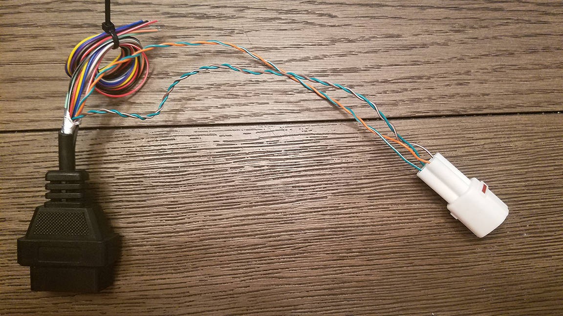
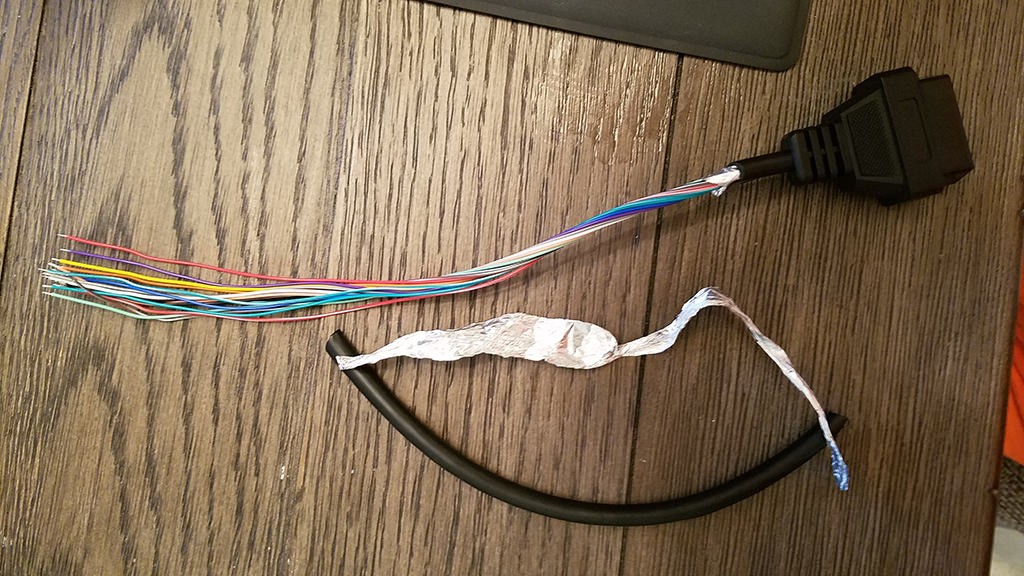 Stripped sheath and shielding
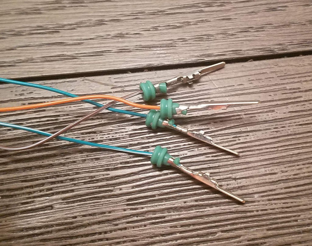
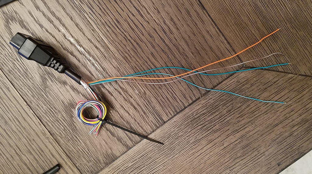 Separated 4 wires being used
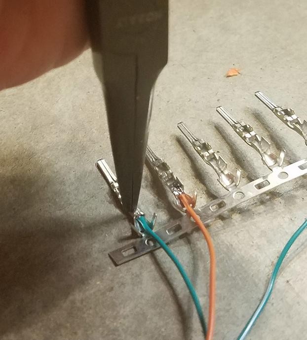
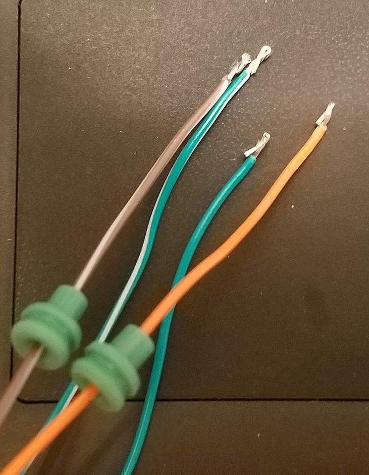 Wires for the 4PC
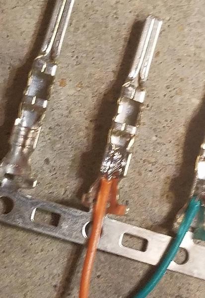
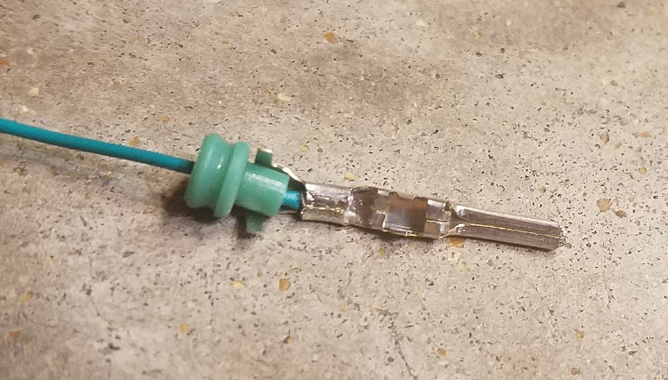
 Wiring is small compared to the pin connector
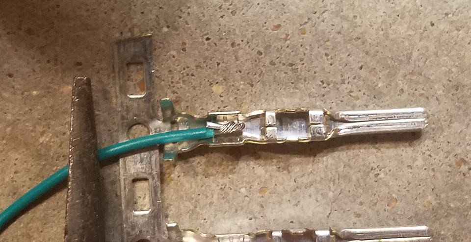
 Solder the wire to the pin connector
 Fold one of the prongs over onto the wire
 Crush the prongs down a bit further
 Fold the prongs over the seal
 Use the same technique as before to fold the prongs over the seal
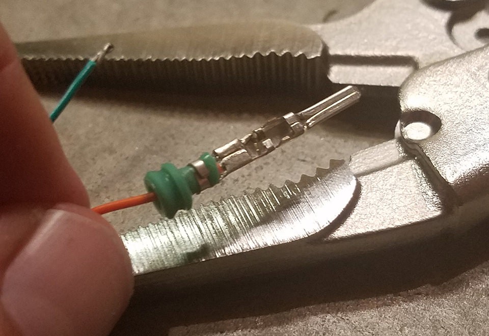
 Pliers to crush the prongs down a bit further
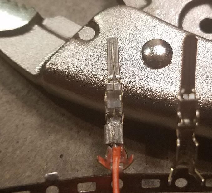
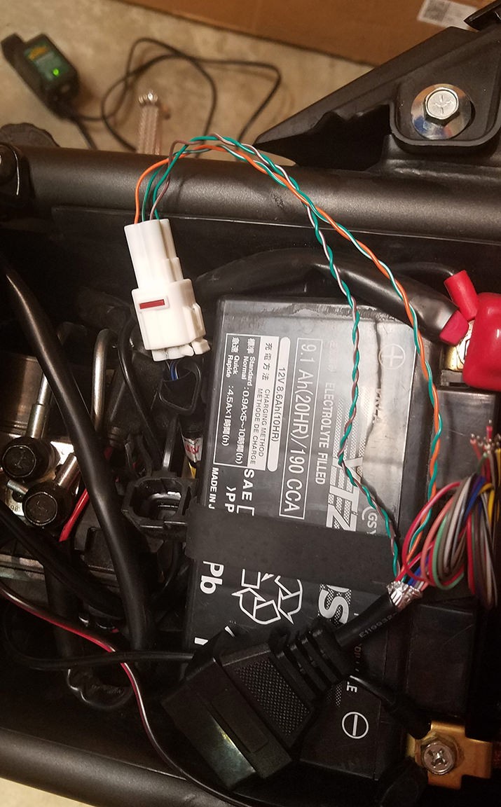
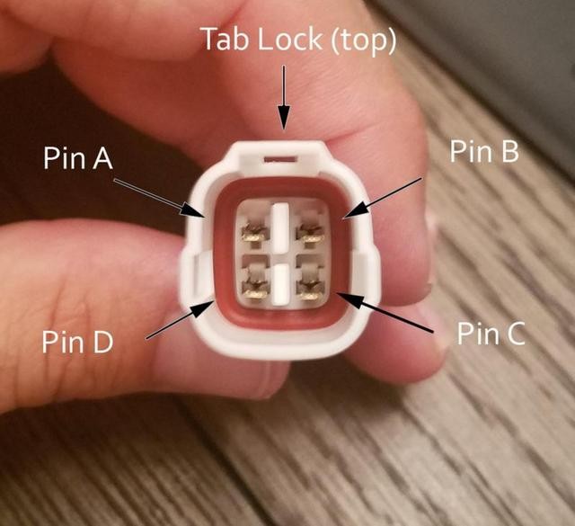 Insert the pins into the 4PC
 Successfully tested
 Check an error and clear it