The H22 Obd1 To Obd2 Distributor Wiring involves creating a subharness to connect the OBD1 distributor to your OBD2 vehicle. This process, while intricate, ensures your engine runs smoothly by correctly simulating the necessary sensor signals. At OBD2-SCANNER.EDU.VN, we provide the insights and tools you need to navigate this conversion efficiently, including comprehensive guides and support for various automotive diagnostic and repair tasks.
Contents
- 1. Understanding the H22 OBD1 to OBD2 Distributor Wiring Challenge
- 1.1. What Are the Key Differences Between OBD1 and OBD2 Distributor Systems?
- 1.2. Why Is Proper Wiring Crucial for Engine Performance?
- 1.3. What Are the Consequences of Incorrect Wiring?
- 2. Essential Components for the H22 OBD1 to OBD2 Distributor Wiring
- 2.1. Identifying the Necessary Parts and Tools
- 2.2. Understanding the Role of the Crank Position Sensor (CKP)
- 2.3. The Importance of the Top Dead Center (TDC) Sensor
- 2.4. How the Ignition Control Module (ICM) Works
- 3. Step-by-Step Guide to Wiring the H22 OBD1 Distributor
- 3.1. Preparing the OBD1 Distributor for Wiring
- 3.2. Creating a Custom Subharness
- 3.3. Connecting the CKP and TDC Sensors
- 3.4. Wiring the Ignition Control Module (ICM)
- 3.5. Ensuring Proper Grounding
- 4. Advanced Techniques for H22 OBD1 to OBD2 Distributor Wiring
- 4.1. Using an Oscilloscope for Signal Verification
- 4.2. Shielding Wires to Reduce Interference
- 4.3. Implementing Noise Filters
- 4.4. Ensuring Proper Wire Gauge
- 4.5. Using High-Quality Connectors and Terminals
- 5. Troubleshooting Common Issues After Wiring
- 5.1. Identifying Misfire Codes
- 5.2. Addressing Issues with the Check Engine Light
- 5.3. Resolving Poor Engine Performance
- 5.4. Diagnosing Sensor Signal Problems
- 5.5. Ensuring Proper Voltage Levels
- 6. Maintaining Your H22 OBD1 to OBD2 Distributor Wiring
- 6.1. Regular Inspections for Wear and Tear
- 6.2. Protecting Wires from Environmental Damage
- 6.3. Cleaning Connectors and Terminals
- 6.4. Ensuring Proper Wire Routing
- 6.5. Monitoring Engine Performance
- 7. Benefits of Professional Diagnostic Services
- 7.1. Expertise and Experience
- 7.2. Advanced Diagnostic Tools
- 7.3. Time Savings
- 7.4. Cost-Effectiveness
- 7.5. Peace of Mind
- 8. Frequently Asked Questions (FAQs)
- 8.1. What is an OBD2 Scanner?
- 8.2. How Do I Read OBD2 Error Codes?
- 8.3. What Are Common Car Problems and How Can I Fix Them?
- 8.4. Can I Use an OBD1 Distributor on an OBD2 System?
- 8.5. What Tools Do I Need for Distributor Wiring?
- 8.6. How Important Is Proper Grounding?
- 8.7. What Are the Symptoms of Incorrect Wiring?
- 8.8. Can I Shield Wires to Reduce Interference?
- 8.9. How Often Should I Inspect My Wiring?
- 8.10. Where Can I Find Professional Diagnostic Services?
- 9. Get Expert Assistance with Your H22 OBD1 to OBD2 Wiring Project
1. Understanding the H22 OBD1 to OBD2 Distributor Wiring Challenge
When swapping an older OBD1 (On-Board Diagnostics 1) H22 engine into a newer OBD2 (On-Board Diagnostics 2) vehicle, one of the main hurdles is getting the distributor wiring correct. OBD1 and OBD2 systems use different sensors and wiring configurations. This difference means a direct plug-and-play connection isn’t possible, making a custom wiring solution necessary. This conversion ensures compatibility between the engine’s sensors and the car’s computer.
1.1. What Are the Key Differences Between OBD1 and OBD2 Distributor Systems?
OBD1 systems are generally simpler, often relying on fewer sensors and less complex wiring setups compared to OBD2 systems. According to a study by the Society of Automotive Engineers (SAE), OBD2 systems, introduced in the mid-1990s, were designed to offer more comprehensive diagnostics and emission control. This advancement required more sophisticated sensors and a standardized communication protocol. Key differences include:
- Sensor Types: OBD1 distributors often combine multiple sensor functions into a single unit, while OBD2 systems separate these functions into individual sensors.
- Wiring Complexity: OBD2 systems typically have more wires and connectors to accommodate the increased number of sensors.
- Diagnostic Capabilities: OBD2 provides more detailed diagnostic information, including specific fault codes for various engine and emission-related issues.
1.2. Why Is Proper Wiring Crucial for Engine Performance?
Correct wiring ensures that the engine control unit (ECU) receives accurate signals from all necessary sensors. Proper communication between the sensors and ECU is vital for:
- Timing and Ignition: The distributor sends signals about crankshaft position and cylinder identification, which the ECU uses to control spark timing and fuel injection.
- Fuel Efficiency: Accurate sensor data allows the ECU to optimize the fuel-air mixture, improving fuel economy.
- Emissions Control: Proper wiring helps the ECU manage emissions by ensuring the catalytic converter and other emission control devices function correctly.
- Preventing Damage: Incorrect wiring can lead to misfires, poor performance, and potentially damage the engine or ECU.
1.3. What Are the Consequences of Incorrect Wiring?
Incorrect wiring can lead to a range of problems, from minor inconveniences to major engine damage. Some potential consequences include:
- Engine Misfires: Incorrect timing or cylinder identification can cause the engine to misfire, leading to rough running and reduced power.
- Poor Fuel Economy: An improperly tuned fuel-air mixture can significantly reduce fuel efficiency.
- Check Engine Light: The ECU will detect discrepancies in sensor readings and trigger the check engine light, potentially storing diagnostic trouble codes (DTCs).
- Engine Damage: In severe cases, incorrect wiring can cause damage to engine components such as pistons, valves, or the catalytic converter.
- ECU Damage: Sending incorrect voltage or signals to the ECU can damage its internal components, requiring costly repairs or replacement.
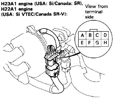 OBD1 Prelude Distributor
2. Essential Components for the H22 OBD1 to OBD2 Distributor Wiring
Successfully wiring an H22 OBD1 distributor to an OBD2 system requires several key components and a good understanding of their functions. These components ensure compatibility and proper signal transmission between the engine and the vehicle’s ECU.
2.1. Identifying the Necessary Parts and Tools
Before starting the wiring process, gather all the necessary parts and tools. This preparation will help ensure a smooth and efficient conversion. Essential items include:
- OBD1 Distributor: The distributor from the H22 OBD1 engine, which contains the necessary sensors for timing and ignition.
- OBD2 Vehicle Harness: The existing wiring harness in the OBD2 vehicle that needs to be adapted to connect to the OBD1 distributor.
- Subharness Components: Wires, connectors, and pins to create a subharness that bridges the gap between the OBD1 distributor and the OBD2 harness.
- Wiring Diagram: A detailed wiring diagram for both the OBD1 distributor and the OBD2 vehicle, showing the pinouts and functions of each wire.
- Soldering Iron and Solder: For making secure and reliable electrical connections.
- Wire Strippers and Crimpers: To prepare the wires and attach connectors properly.
- Multimeter: To test continuity and voltage levels, ensuring the wiring is correct and functional.
- Heat Shrink Tubing or Electrical Tape: To insulate and protect the connections from moisture and corrosion.
2.2. Understanding the Role of the Crank Position Sensor (CKP)
The Crank Position Sensor (CKP) is crucial for engine timing and operation. According to a study by Bosch, the CKP provides the ECU with real-time information about the crankshaft’s position and speed, which is essential for:
- Ignition Timing: The ECU uses CKP data to determine when to fire the spark plugs, ensuring optimal combustion.
- Fuel Injection Timing: CKP data is also used to time the fuel injectors, ensuring the correct amount of fuel is delivered to each cylinder at the right moment.
- Engine Speed (RPM) Measurement: The CKP signal allows the ECU to monitor engine speed, which is critical for various engine control functions.
2.3. The Importance of the Top Dead Center (TDC) Sensor
The Top Dead Center (TDC) sensor, also known as the Cylinder Position Sensor (CYP), identifies when the first cylinder is at its highest point (TDC) in the compression stroke. The TDC sensor helps the ECU:
- Cylinder Identification: By knowing the position of the first cylinder, the ECU can accurately time the firing order of the engine.
- Sequential Fuel Injection: TDC information enables sequential fuel injection, where fuel is injected into each cylinder at the precise moment it needs it.
- Optimized Engine Performance: Accurate cylinder identification and timing lead to smoother engine operation, better fuel economy, and reduced emissions.
2.4. How the Ignition Control Module (ICM) Works
The Ignition Control Module (ICM) is responsible for controlling the ignition coil based on signals from the ECU. The ICM plays a critical role in:
- Spark Generation: The ICM receives a signal from the ECU and triggers the ignition coil to generate a high-voltage spark, which is then sent to the spark plugs.
- Dwell Time Control: The ICM controls the dwell time, which is the amount of time the ignition coil is charged before firing. Proper dwell time is essential for generating a strong spark.
- Ignition System Reliability: The ICM ensures the ignition system operates reliably and efficiently, contributing to overall engine performance.
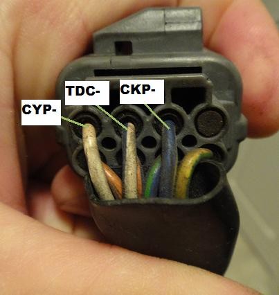 OBD1 Plug
3. Step-by-Step Guide to Wiring the H22 OBD1 Distributor
Wiring an H22 OBD1 distributor to an OBD2 system involves several key steps, including preparing the distributor, creating a subharness, and connecting the necessary wires. This process ensures proper signal transmission and engine operation.
3.1. Preparing the OBD1 Distributor for Wiring
Before starting the wiring process, ensure the OBD1 distributor is in good working condition and properly prepared.
- Inspect the Distributor: Check for any signs of damage, such as cracks, corrosion, or broken connectors. Replace any damaged parts.
- Clean the Distributor: Clean the distributor cap and rotor to ensure good electrical contact.
- Identify the Pinouts: Refer to the OBD1 wiring diagram to identify the function of each pin on the distributor connector. Common pins include CKP, TDC, ICM, and power/ground connections.
3.2. Creating a Custom Subharness
A custom subharness acts as an adapter, bridging the gap between the OBD1 distributor and the OBD2 vehicle harness.
- Gather the Components: Collect the necessary wires, connectors, and pins. Use high-quality automotive-grade wire to ensure durability and reliability.
- Prepare the Wires: Cut the wires to the appropriate length, strip the ends, and crimp or solder the pins onto the wires.
- Connect the Wires: Refer to the wiring diagrams for both the OBD1 distributor and the OBD2 vehicle. Connect the corresponding wires, matching the function of each pin. For example, connect the CKP wire from the OBD1 distributor to the CKP wire in the OBD2 harness.
- Insulate the Connections: Use heat shrink tubing or electrical tape to insulate the connections, protecting them from moisture and corrosion.
3.3. Connecting the CKP and TDC Sensors
The Crank Position Sensor (CKP) and Top Dead Center (TDC) sensors are critical for engine timing and operation.
- Locate the CKP and TDC Wires: Identify the CKP and TDC wires on both the OBD1 distributor and the OBD2 vehicle harness.
- Connect the Wires: Connect the CKP wire from the OBD1 distributor to the CKP wire in the OBD2 harness. Repeat this process for the TDC wire.
- Verify the Connections: Use a multimeter to verify the continuity of the connections, ensuring the signals can pass through the wires.
3.4. Wiring the Ignition Control Module (ICM)
The Ignition Control Module (ICM) controls the ignition coil, which generates the spark for the engine.
- Identify the ICM Wire: Locate the ICM wire on both the OBD1 distributor and the OBD2 vehicle harness.
- Connect the Wires: Connect the ICM wire from the OBD1 distributor to the ICM wire in the OBD2 harness.
- Check the Voltage: Use a multimeter to check the voltage at the ICM wire, ensuring it is receiving the correct voltage from the ECU.
3.5. Ensuring Proper Grounding
Proper grounding is essential for the reliable operation of the distributor and sensors.
- Locate the Ground Wires: Identify the ground wires on both the OBD1 distributor and the OBD2 vehicle harness.
- Connect the Ground Wires: Connect the ground wire from the OBD1 distributor to a suitable ground point in the OBD2 vehicle. Ensure the ground point is clean and free from corrosion.
- Test the Ground Connection: Use a multimeter to test the resistance between the ground wire and the vehicle chassis, ensuring a good ground connection.
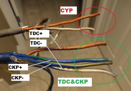 Other End of Wires
4. Advanced Techniques for H22 OBD1 to OBD2 Distributor Wiring
For those looking to optimize their H22 OBD1 to OBD2 distributor wiring, several advanced techniques can improve performance and reliability. These methods involve using specialized tools, understanding advanced wiring concepts, and implementing best practices for wire management and protection.
4.1. Using an Oscilloscope for Signal Verification
An oscilloscope is an invaluable tool for verifying the signals from the CKP, TDC, and ICM sensors. According to a study by Tektronix, an oscilloscope can display the waveform of electrical signals, allowing technicians to:
- Check Signal Integrity: Ensure the signals are clean and free from noise or interference.
- Measure Signal Amplitude and Frequency: Verify the signals are within the specified range, indicating proper sensor operation.
- Diagnose Signal Issues: Identify problems such as missing signals, distorted waveforms, or incorrect timing.
To use an oscilloscope, connect the probes to the appropriate wires and observe the waveform while the engine is running. Compare the waveform to a known good signal to identify any discrepancies.
4.2. Shielding Wires to Reduce Interference
Electrical interference can disrupt the signals from the sensors, leading to inaccurate readings and poor engine performance. Shielding wires can help reduce this interference.
- Use Shielded Wire: Replace the standard wire with shielded wire, which has a layer of conductive material (usually copper or aluminum) surrounding the inner conductor.
- Ground the Shield: Connect the shield to a good ground point in the vehicle. This will divert the interference to ground, preventing it from affecting the signal.
- Keep Wires Away from Noise Sources: Route the wires away from potential sources of interference, such as the ignition coil, alternator, and other high-voltage components.
4.3. Implementing Noise Filters
Noise filters can further reduce electrical noise and improve signal quality. These filters are designed to block unwanted frequencies, allowing the desired signal to pass through.
- Choose the Right Filter: Select a noise filter that is appropriate for the frequency range of the sensor signals.
- Install the Filter: Connect the filter in series with the sensor wire, close to the ECU.
- Test the Signal: Use an oscilloscope to verify that the filter is reducing noise without distorting the signal.
4.4. Ensuring Proper Wire Gauge
Using the correct wire gauge is essential for ensuring the proper flow of current and voltage to the distributor and sensors.
- Refer to the Wiring Diagram: Consult the wiring diagram to determine the recommended wire gauge for each circuit.
- Use the Correct Wire: Use wire that is the same gauge or slightly larger than the recommended gauge. Avoid using wire that is too small, as it can cause voltage drop and overheating.
- Check for Voltage Drop: Use a multimeter to check for voltage drop in the circuits. Excessive voltage drop indicates the wire is too small or there is a poor connection.
4.5. Using High-Quality Connectors and Terminals
High-quality connectors and terminals ensure reliable electrical connections and prevent corrosion.
- Choose Weatherproof Connectors: Use weatherproof connectors that are designed to withstand the harsh conditions in the engine bay.
- Use Properly Crimped Terminals: Use a quality crimping tool to ensure the terminals are properly attached to the wires. A poor crimp can cause loose connections and corrosion.
- Apply Dielectric Grease: Apply dielectric grease to the connectors to prevent moisture and corrosion.
5. Troubleshooting Common Issues After Wiring
After wiring the H22 OBD1 distributor to an OBD2 system, several issues may arise. Troubleshooting these problems effectively requires a systematic approach and the right tools.
5.1. Identifying Misfire Codes
Misfire codes are among the most common issues after wiring a distributor. These codes indicate that one or more cylinders are not firing correctly.
- Read the Codes: Use an OBD2 scanner to read the diagnostic trouble codes (DTCs) stored in the ECU. Common misfire codes include P0300 (Random Misfire), P0301 (Cylinder 1 Misfire), P0302 (Cylinder 2 Misfire), and so on.
- Check the Wiring: Inspect the wiring to the distributor, CKP, TDC, and ICM. Look for loose connections, damaged wires, or corrosion.
- Verify the Sensor Signals: Use an oscilloscope to verify the signals from the CKP, TDC, and ICM sensors. Ensure the signals are clean and within the specified range.
- Check the Spark Plugs: Inspect the spark plugs for wear or damage. Replace the spark plugs if necessary.
- Check the Ignition Coil: Test the ignition coil to ensure it is generating a strong spark. Replace the ignition coil if necessary.
5.2. Addressing Issues with the Check Engine Light
The Check Engine Light (CEL) can illuminate for a variety of reasons after wiring a distributor.
- Read the Codes: Use an OBD2 scanner to read the DTCs stored in the ECU.
- Research the Codes: Research the codes to understand the potential causes of the problem.
- Check the Wiring: Inspect the wiring to all relevant sensors and components.
- Verify the Sensor Signals: Use an oscilloscope or multimeter to verify the signals from the sensors.
- Clear the Codes: After addressing the issue, clear the codes from the ECU and monitor the vehicle to see if the CEL returns.
5.3. Resolving Poor Engine Performance
Poor engine performance, such as rough idling, reduced power, or poor fuel economy, can occur after wiring a distributor.
- Check the Timing: Verify the ignition timing using a timing light. Adjust the timing if necessary.
- Check the Fuel System: Inspect the fuel injectors, fuel pump, and fuel filter to ensure they are functioning correctly.
- Check the Air Intake System: Inspect the air filter, throttle body, and intake manifold for any obstructions or leaks.
- Check the Compression: Perform a compression test to check the health of the engine cylinders.
5.4. Diagnosing Sensor Signal Problems
Sensor signal problems can lead to a variety of issues, including misfires, poor performance, and the CEL.
- Use an Oscilloscope: Use an oscilloscope to observe the waveforms of the sensor signals.
- Check for Noise: Look for excessive noise or interference in the signals.
- Verify Amplitude and Frequency: Measure the amplitude and frequency of the signals to ensure they are within the specified range.
- Check for Continuity: Use a multimeter to check for continuity in the sensor circuits.
5.5. Ensuring Proper Voltage Levels
Proper voltage levels are essential for the correct operation of the distributor and sensors.
- Check the Voltage at the Distributor: Use a multimeter to check the voltage at the distributor connector.
- Check the Voltage at the Sensors: Use a multimeter to check the voltage at the sensor connectors.
- Check for Voltage Drop: Check for voltage drop in the circuits. Excessive voltage drop indicates a problem with the wiring or connections.
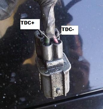 TDC CKP Sensor Clip
6. Maintaining Your H22 OBD1 to OBD2 Distributor Wiring
Proper maintenance is crucial to ensure the longevity and reliability of your H22 OBD1 to OBD2 distributor wiring. Regular inspections and preventative measures can help avoid common issues and keep your engine running smoothly.
6.1. Regular Inspections for Wear and Tear
Regularly inspecting your wiring can help identify potential problems before they lead to major issues.
- Visual Inspection: Perform a visual inspection of the wiring, connectors, and terminals. Look for signs of wear, damage, or corrosion.
- Check for Loose Connections: Check for loose connections at the distributor, sensors, and ECU.
- Inspect the Wiring Harness: Inspect the wiring harness for any signs of damage, such as cracks, cuts, or abrasions.
- Check the Ground Connections: Check the ground connections to ensure they are clean and secure.
6.2. Protecting Wires from Environmental Damage
Protecting wires from environmental damage, such as heat, moisture, and chemicals, can significantly extend their lifespan.
- Use Protective Sleeving: Use protective sleeving, such as heat shrink tubing or split loom tubing, to protect the wires from abrasion and heat.
- Route Wires Away from Heat Sources: Route the wires away from heat sources, such as the exhaust manifold and engine block.
- Use Weatherproof Connectors: Use weatherproof connectors to protect the connections from moisture and corrosion.
- Apply Dielectric Grease: Apply dielectric grease to the connectors to prevent moisture and corrosion.
6.3. Cleaning Connectors and Terminals
Cleaning connectors and terminals can help maintain good electrical contact and prevent corrosion.
- Disconnect the Connectors: Disconnect the connectors from the distributor, sensors, and ECU.
- Clean the Terminals: Use a wire brush or terminal cleaning tool to clean the terminals.
- Apply Dielectric Grease: Apply dielectric grease to the terminals before reconnecting the connectors.
6.4. Ensuring Proper Wire Routing
Proper wire routing can help prevent damage and interference.
- Keep Wires Away from Moving Parts: Route the wires away from moving parts, such as the belts, pulleys, and fan.
- Secure the Wires: Secure the wires with zip ties or clips to prevent them from rubbing against sharp edges or vibrating.
- Follow the Factory Routing: Follow the factory routing as closely as possible to ensure the wires are properly protected and supported.
6.5. Monitoring Engine Performance
Monitoring engine performance can help identify potential issues with the distributor wiring.
- Pay Attention to the Check Engine Light: Pay attention to the Check Engine Light and investigate any codes that are stored in the ECU.
- Monitor Fuel Economy: Monitor fuel economy and investigate any sudden changes.
- Listen for Unusual Noises: Listen for unusual noises, such as misfires or rough idling.
- Check for Reduced Power: Check for reduced power or poor acceleration.
 CKP TDC Wires Connected
7. Benefits of Professional Diagnostic Services
While this guide provides comprehensive information on H22 OBD1 to OBD2 distributor wiring, professional diagnostic services can offer significant benefits, especially for those who are not experienced with automotive electrical systems.
7.1. Expertise and Experience
Professional technicians have the expertise and experience to accurately diagnose and resolve complex wiring issues. They understand the intricacies of automotive electrical systems and can quickly identify problems that may be difficult for a novice to detect.
7.2. Advanced Diagnostic Tools
Professional diagnostic services have access to advanced diagnostic tools, such as oscilloscopes, scan tools, and specialized testing equipment. These tools allow them to accurately measure sensor signals, identify wiring faults, and diagnose engine performance issues.
7.3. Time Savings
Diagnosing and repairing wiring issues can be time-consuming, especially for those who are not familiar with automotive electrical systems. Professional technicians can quickly identify the problem and perform the necessary repairs, saving you time and hassle.
7.4. Cost-Effectiveness
While professional diagnostic services may seem expensive, they can be cost-effective in the long run. By accurately diagnosing and resolving the problem, they can prevent further damage to the engine or electrical system.
7.5. Peace of Mind
Knowing that your vehicle is being serviced by a qualified professional can give you peace of mind. You can be confident that the wiring is being done correctly and that your engine is running safely and reliably.
8. Frequently Asked Questions (FAQs)
Here are some frequently asked questions about H22 OBD1 to OBD2 distributor wiring:
8.1. What is an OBD2 Scanner?
An OBD2 scanner is a diagnostic tool used to retrieve information from a vehicle’s On-Board Diagnostic system. It helps identify issues by reading diagnostic trouble codes (DTCs) and other data.
8.2. How Do I Read OBD2 Error Codes?
To read OBD2 error codes, plug the scanner into the OBD2 port (usually under the dashboard), turn on the ignition, and follow the scanner’s instructions to retrieve the codes.
8.3. What Are Common Car Problems and How Can I Fix Them?
Common car problems include engine misfires, faulty sensors, and electrical issues. These can often be diagnosed using an OBD2 scanner and fixed by replacing faulty parts or repairing wiring.
8.4. Can I Use an OBD1 Distributor on an OBD2 System?
Yes, but it requires custom wiring to ensure compatibility between the distributor’s sensors and the vehicle’s ECU.
8.5. What Tools Do I Need for Distributor Wiring?
Essential tools include wire strippers, crimpers, a soldering iron, a multimeter, and a detailed wiring diagram.
8.6. How Important Is Proper Grounding?
Proper grounding is critical for the reliable operation of the distributor and sensors. A poor ground connection can lead to inaccurate readings and performance issues.
8.7. What Are the Symptoms of Incorrect Wiring?
Symptoms of incorrect wiring include engine misfires, poor fuel economy, the Check Engine Light, and reduced engine power.
8.8. Can I Shield Wires to Reduce Interference?
Yes, shielding wires can help reduce electrical interference and improve signal quality.
8.9. How Often Should I Inspect My Wiring?
Regular inspections, at least every six months, can help identify potential problems before they lead to major issues.
8.10. Where Can I Find Professional Diagnostic Services?
Professional diagnostic services are available at reputable auto repair shops and dealerships. You can also contact OBD2-SCANNER.EDU.VN for expert assistance.
9. Get Expert Assistance with Your H22 OBD1 to OBD2 Wiring Project
At OBD2-SCANNER.EDU.VN, we understand the complexities of automotive wiring and diagnostics. Whether you’re tackling an H22 OBD1 to OBD2 distributor wiring project or need help diagnosing a Check Engine Light, our team of experienced technicians is here to assist you.
Why Choose OBD2-SCANNER.EDU.VN?
- Expert Technicians: Our technicians have years of experience working with automotive electrical systems.
- Advanced Tools: We use state-of-the-art diagnostic tools to accurately identify and resolve wiring issues.
- Comprehensive Support: We offer comprehensive support, from wiring diagrams to troubleshooting tips.
- Customer Satisfaction: We are committed to providing the highest level of customer satisfaction.
Contact Us Today
Don’t let wiring issues keep you off the road. Contact OBD2-SCANNER.EDU.VN today for expert assistance with your H22 OBD1 to OBD2 distributor wiring project.
- Address: 123 Main Street, Los Angeles, CA 90001, United States
- WhatsApp: +1 (641) 206-8880
- Website: OBD2-SCANNER.EDU.VN
We are here to help you get your engine running smoothly and reliably. Contact us today to learn more about our services and how we can assist you.
By choosing OBD2-SCANNER.EDU.VN, you can be confident that your H22 OBD1 to OBD2 distributor wiring project will be done right. Our expertise, advanced tools, and commitment to customer satisfaction make us the ideal partner for all your automotive diagnostic and repair needs.