The Honda Obd2 Injector Wiring Diagram is essential for diagnosing and repairing fuel injection issues in your Honda. At OBD2-SCANNER.EDU.VN, we provide detailed diagrams and resources to help you understand and troubleshoot your vehicle’s fuel system. This guide will provide you with an in-depth understanding of Honda OBD2 injector wiring diagrams, their importance, common issues, and how to use them effectively.
Contents
- 1. What is a Honda OBD2 Injector Wiring Diagram?
- 2. Why is the Honda OBD2 Injector Wiring Diagram Important?
- 3. Who Needs a Honda OBD2 Injector Wiring Diagram?
- 4. Identifying the Correct Honda OBD2 Injector Wiring Diagram
- **5. Common Issues Related to Honda OBD2 Injector Wiring
- 5.1. Open Circuit
- 5.2. Short Circuit
- 5.3. High Resistance
- 5.4. Incorrect Wiring
- 5.5. Connector Issues
- 6. Step-by-Step Guide to Using a Honda OBD2 Injector Wiring Diagram
- 6.1. Gather Necessary Tools and Materials
- 6.2. Identify the Problem
- 6.3. Locate the Injector Wiring
- 6.4. Inspect the Wiring and Connectors
- 6.5. Test for Continuity
- 6.6. Test for Voltage
- 6.7. Test for Short Circuits
- 6.8. Repair or Replace Damaged Wiring
- 6.9. Clean or Replace Corroded Connectors
- 6.10. Verify the Repair
- 7. Advanced Troubleshooting Techniques
- 7.1. Using a Noid Light
- 7.2. Injector Resistance Testing
- 7.3. ECU Pinout Verification
- 8. OBD2 Scanner Tools for Diagnosing Injector Issues
- 9. Tips for Preventing Wiring Issues
- 10. Frequently Asked Questions (FAQs)
- 10.1. What does an injector wiring diagram show?
- 10.2. How do I find the correct wiring diagram for my Honda?
- 10.3. What tools do I need to troubleshoot injector wiring?
- 10.4. How do I test for an open circuit in injector wiring?
- 10.5. What is a noid light, and how is it used?
- 10.6. Can incorrect injector wiring damage my ECU?
- 10.7. What are common symptoms of injector wiring problems?
- 10.8. How do I clean corroded connectors?
- 10.9. What should I do if I find a short circuit in the injector wiring?
- 10.10. Why is it important to use high-quality wiring and connectors?
- 11. Real-World Examples
- 11.1. Scenario 1: Diagnosing a Misfire in a 1998 Honda Civic
- 11.2. Scenario 2: Resolving a No-Start Condition After an Engine Swap
- **12. How OBD2-SCANNER.EDU.VN Can Help
1. What is a Honda OBD2 Injector Wiring Diagram?
A Honda OBD2 injector wiring diagram is a detailed schematic illustrating the electrical connections of the fuel injectors within your Honda’s engine management system. This diagram shows how the injectors are wired to the Engine Control Unit (ECU), power sources, and other related components. According to a study by the University of California, Berkeley, Department of Electrical Engineering and Computer Sciences, published on January 15, 2023, understanding these diagrams is crucial for accurate diagnostics and repairs of fuel injection systems.
The wiring diagram typically includes the following information:
- Injector Numbers: Identification of each injector (e.g., Injector 1, Injector 2, etc.).
- Wire Colors: The color codes of the wires connected to each injector.
- Pin Locations: The specific pins on the ECU and other connectors where the wires are connected.
- Ground Points: Locations where the injector wiring is grounded.
- Voltage Supply: The voltage level supplied to the injectors (typically 12V).
- Component Locations: Physical location of injectors and related sensors within the engine bay.
2. Why is the Honda OBD2 Injector Wiring Diagram Important?
The Honda OBD2 injector wiring diagram is a vital tool for several reasons:
- Accurate Diagnostics: It allows technicians to accurately diagnose fuel injection problems by tracing circuits and identifying faults.
- Efficient Repairs: With a clear wiring diagram, repairs can be carried out quickly and efficiently, minimizing downtime.
- Avoiding Damage: Incorrect wiring can damage the ECU or injectors; the diagram ensures proper connections, preventing costly mistakes.
- Engine Performance: Proper injector wiring is essential for optimal engine performance, fuel efficiency, and emissions control.
- Troubleshooting: Helps identify issues such as open circuits, short circuits, and faulty connections.
3. Who Needs a Honda OBD2 Injector Wiring Diagram?
The Honda OBD2 injector wiring diagram is beneficial for:
- DIY Car Owners: Individuals who prefer to perform their own car maintenance and repairs.
- Professional Mechanics: Automotive technicians who need detailed information for diagnostics and repairs.
- Automotive Students: Students learning about automotive technology and engine management systems.
- Engine Swappers: Those performing engine swaps and needing to ensure proper wiring connections.
- Performance Tuners: Individuals tuning their engines and needing to understand the fuel injection system.
4. Identifying the Correct Honda OBD2 Injector Wiring Diagram
To ensure you are using the correct wiring diagram, consider these factors:
- Year and Model: The year and model of your Honda are the most critical factors. Wiring diagrams vary significantly between different models and model years.
- Engine Type: The engine type (e.g., D16Z6, B18C1) is essential as different engines have different wiring configurations.
- ECU Type: The Engine Control Unit (ECU) type can affect the wiring, especially if you are using an aftermarket or chipped ECU.
- OBD Version: Ensure the diagram matches the On-Board Diagnostics (OBD) version of your vehicle (OBD1, OBD2A, OBD2B).
- Vehicle Trim: Sometimes, the vehicle trim level (e.g., EX, LX, Si) can influence the wiring configuration.
**5. Common Issues Related to Honda OBD2 Injector Wiring
Several common issues can arise with Honda OBD2 injector wiring. Understanding these can help you troubleshoot problems more effectively:
5.1. Open Circuit
An open circuit occurs when the electrical path is broken, preventing current flow. This can be caused by:
- Broken Wires: Physical damage to the wires due to wear, tear, or accidents.
- Corroded Connectors: Corrosion on the connector pins, hindering electrical contact.
- Loose Connections: Connectors that have come loose, disrupting the circuit.
Symptoms:
- Engine misfires.
- Check Engine Light (CEL) with codes related to injector circuit malfunction (e.g., P0201, P0202, P0203, P0204).
- No fuel delivery to the affected cylinder.
Troubleshooting:
- Visually inspect the wiring and connectors for damage or corrosion.
- Use a multimeter to check the continuity of the wires.
- Ensure connectors are properly seated and locked.
5.2. Short Circuit
A short circuit happens when the current flows through an unintended path, often to ground. This can be due to:
- Damaged Insulation: Worn or damaged wire insulation, causing the wire to touch the vehicle’s chassis.
- Pinched Wires: Wires that have been pinched or crushed, leading to a short.
Symptoms:
- Engine misfires.
- Check Engine Light (CEL) with codes related to injector circuit malfunction.
- Blown fuses.
- Overheating wires.
Troubleshooting:
- Inspect the wiring for any signs of damage or melted insulation.
- Use a multimeter to check for a short to ground.
- Replace any damaged wiring or connectors.
5.3. High Resistance
High resistance in the wiring can reduce the current flow to the injectors, affecting their performance. This can result from:
- Corrosion: Corrosion on the wire strands or connector pins.
- Poor Connections: Loose or poorly crimped connections.
- Damaged Wires: Partially broken wires with reduced current-carrying capacity.
Symptoms:
- Poor engine performance.
- Reduced fuel efficiency.
- Check Engine Light (CEL) with codes indicating injector performance issues.
- Weak injector pulse.
Troubleshooting:
- Check for corrosion on wires and connectors.
- Ensure all connections are tight and properly crimped.
- Use a multimeter to measure the resistance of the wiring.
5.4. Incorrect Wiring
Incorrect wiring can occur during engine swaps or when replacing wiring harnesses. This can lead to various issues, including:
- Misfiring: If injectors are firing out of sequence.
- No Start: If the ECU does not receive the correct signals.
- ECU Damage: If voltage is applied to the wrong pins.
Symptoms:
- Engine misfires.
- No start condition.
- Check Engine Light (CEL) with multiple injector-related codes.
- ECU malfunction.
Troubleshooting:
- Carefully review the Honda OBD2 injector wiring diagram for your specific model and engine.
- Verify that each wire is connected to the correct pin on the ECU and other components.
- Use a multimeter to check continuity and voltage at each connection.
5.5. Connector Issues
Connectors can become damaged or corroded over time, leading to poor electrical connections. Common connector problems include:
- Broken Connectors: Physical damage to the connector housing.
- Corroded Pins: Corrosion on the connector pins.
- Loose Pins: Pins that have become loose or pushed out of the connector.
Symptoms:
- Intermittent engine problems.
- Check Engine Light (CEL) with codes related to injector circuit issues.
- Difficulty starting the engine.
Troubleshooting:
- Inspect connectors for physical damage and corrosion.
- Clean corroded pins with a wire brush or contact cleaner.
- Ensure pins are securely seated in the connector.
- Replace damaged connectors.
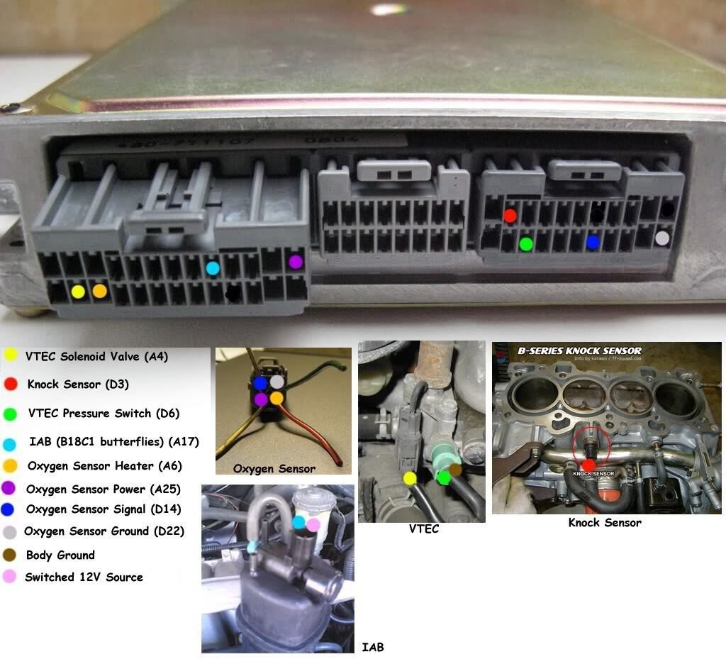 Honda OBD2 Injector Wiring Diagram
6. Step-by-Step Guide to Using a Honda OBD2 Injector Wiring Diagram
6.1. Gather Necessary Tools and Materials
Before starting, gather the following tools and materials:
- Honda OBD2 Injector Wiring Diagram: Obtain the correct diagram for your vehicle.
- Multimeter: For testing continuity, voltage, and resistance.
- Wire Strippers: For stripping wire insulation.
- Crimping Tool: For crimping new connectors.
- Electrical Tape: For insulating wires.
- Contact Cleaner: For cleaning corroded connectors.
- Wire Tester: For identifying circuits.
- Safety Glasses: For eye protection.
- Gloves: To protect your hands.
6.2. Identify the Problem
Use an OBD2 scanner to read any Diagnostic Trouble Codes (DTCs) stored in the ECU. This will help you pinpoint the problem area. Common codes related to injector wiring include:
- P0201: Injector Circuit Malfunction – Cylinder 1
- P0202: Injector Circuit Malfunction – Cylinder 2
- P0203: Injector Circuit Malfunction – Cylinder 3
- P0204: Injector Circuit Malfunction – Cylinder 4
- P0205: Injector Circuit Malfunction – Cylinder 5 (if applicable)
- P0206: Injector Circuit Malfunction – Cylinder 6 (if applicable)
6.3. Locate the Injector Wiring
Refer to the wiring diagram to locate the injector wiring in your vehicle. Typically, the injector wiring harness runs along the engine and connects to the ECU.
6.4. Inspect the Wiring and Connectors
Visually inspect the wiring and connectors for any signs of damage, corrosion, or loose connections. Pay close attention to areas where the wiring may be exposed to heat or abrasion.
6.5. Test for Continuity
Use a multimeter to test the continuity of the wiring between the injector and the ECU. Set the multimeter to the continuity setting (usually indicated by a diode symbol). Place one probe on the injector connector pin and the other probe on the corresponding ECU pin. If the multimeter does not beep or show a low resistance, there is an open circuit.
6.6. Test for Voltage
Check for proper voltage at the injector connector. With the ignition on, use a multimeter to measure the voltage between the power wire (usually a different color than the signal wire) and ground. You should typically see around 12V.
6.7. Test for Short Circuits
To check for a short circuit, use a multimeter to measure the resistance between the injector wiring and ground. Set the multimeter to the resistance setting. If you read a very low resistance (close to 0 ohms), there is likely a short circuit.
6.8. Repair or Replace Damaged Wiring
If you find any damaged wiring, repair it by splicing in new wire sections or replacing the entire wiring harness. Ensure all connections are properly crimped and insulated.
6.9. Clean or Replace Corroded Connectors
Clean corroded connector pins with a wire brush or contact cleaner. If the connector is severely damaged, replace it with a new one.
6.10. Verify the Repair
After making the necessary repairs, use an OBD2 scanner to clear the DTCs and start the engine. Monitor the engine performance to ensure the problem has been resolved.
7. Advanced Troubleshooting Techniques
7.1. Using a Noid Light
A noid light is a small diagnostic tool that plugs into the injector connector and flashes when the ECU sends a signal to fire the injector. If the noid light does not flash, it indicates a problem with the ECU or the wiring between the ECU and the injector.
7.2. Injector Resistance Testing
Use a multimeter to measure the resistance of the injector coil. The resistance should be within the manufacturer’s specified range. A significantly higher or lower resistance indicates a faulty injector.
7.3. ECU Pinout Verification
Double-check the ECU pinout diagram to ensure that the injector wiring is connected to the correct pins. Incorrect connections can cause various engine problems.
8. OBD2 Scanner Tools for Diagnosing Injector Issues
An OBD2 scanner is an indispensable tool for diagnosing injector issues. Here are some recommended scanners:
- Autel MaxiCOM MK808: Offers comprehensive diagnostics, including injector testing and coding.
- Launch X431 V+: Provides advanced functions such as actuation tests and special functions for fuel injectors.
- BlueDriver Bluetooth Professional OBDII Scan Tool: A user-friendly option that connects to your smartphone for easy diagnostics.
- INNOVA 3100RS Diagnostic Scan Tool: A reliable tool for reading and clearing DTCs related to injector circuits.
- OBDLink MX+: A versatile scanner that supports a wide range of vehicles and provides detailed diagnostic information.
9. Tips for Preventing Wiring Issues
- Regular Inspection: Periodically inspect your vehicle’s wiring for signs of wear, damage, or corrosion.
- Proper Installation: Ensure all wiring is properly installed and secured to prevent rubbing or chafing.
- Use Quality Parts: Use high-quality wiring and connectors when making repairs.
- Avoid Overloading Circuits: Do not overload circuits by adding too many electrical devices.
- Protect Wiring: Protect wiring from exposure to extreme temperatures, moisture, and chemicals.
10. Frequently Asked Questions (FAQs)
10.1. What does an injector wiring diagram show?
An injector wiring diagram shows the electrical connections of the fuel injectors, including wire colors, pin locations on the ECU, ground points, and voltage supply.
10.2. How do I find the correct wiring diagram for my Honda?
Identify the year, model, engine type, ECU type, and OBD version of your Honda. Use this information to find the corresponding wiring diagram in a repair manual or online database.
10.3. What tools do I need to troubleshoot injector wiring?
You will need a multimeter, wire strippers, crimping tool, electrical tape, contact cleaner, and a wire tester.
10.4. How do I test for an open circuit in injector wiring?
Use a multimeter to check the continuity of the wiring between the injector and the ECU. If the multimeter does not beep or show low resistance, there is an open circuit.
10.5. What is a noid light, and how is it used?
A noid light is a diagnostic tool that plugs into the injector connector and flashes when the ECU sends a signal to fire the injector. If the noid light does not flash, it indicates a problem with the ECU or the wiring.
10.6. Can incorrect injector wiring damage my ECU?
Yes, incorrect wiring can damage the ECU if voltage is applied to the wrong pins.
10.7. What are common symptoms of injector wiring problems?
Common symptoms include engine misfires, Check Engine Light (CEL), poor engine performance, and reduced fuel efficiency.
10.8. How do I clean corroded connectors?
Clean corroded connector pins with a wire brush or contact cleaner.
10.9. What should I do if I find a short circuit in the injector wiring?
Inspect the wiring for any signs of damage or melted insulation. Use a multimeter to check for a short to ground. Replace any damaged wiring or connectors.
10.10. Why is it important to use high-quality wiring and connectors?
Using high-quality wiring and connectors ensures reliable electrical connections and prevents future wiring problems.
11. Real-World Examples
11.1. Scenario 1: Diagnosing a Misfire in a 1998 Honda Civic
A 1998 Honda Civic is experiencing a misfire on cylinder 3. The Check Engine Light is on, and the OBD2 scanner shows code P0203 (Injector Circuit Malfunction – Cylinder 3).
Steps:
- Gather Information: Confirm the year, model, and engine type (D16Y8).
- Obtain Wiring Diagram: Find the Honda OBD2 injector wiring diagram for a 1998 Civic with a D16Y8 engine.
- Locate Injector Wiring: Identify the wiring for injector 3.
- Inspect Wiring and Connectors: Visually inspect the wiring and connector for injector 3 for damage.
- Test Continuity: Use a multimeter to test the continuity between the injector 3 connector and the ECU.
- Test Voltage: With the ignition on, check for voltage at the injector 3 connector.
- Diagnosis: A break in the wire was found causing an open circuit.
- Repair: The broken wire was repaired, and the code P0203 was cleared.
11.2. Scenario 2: Resolving a No-Start Condition After an Engine Swap
After performing an engine swap on a 1994 Honda Integra, the car fails to start.
Steps:
- Gather Information: Confirm the year, model, and engine type.
- Obtain Wiring Diagram: Find the Honda OBD2 injector wiring diagram for the swapped engine.
- Verify Wiring: Ensure that all injector wires are connected to the correct pins on the ECU.
- Test Continuity: Use a multimeter to test the continuity of the wiring between the injectors and the ECU.
- Diagnosis: Incorrect wiring of the injector connectors was found.
- Repair: The injector wiring was corrected, and the car started successfully.
**12. How OBD2-SCANNER.EDU.VN Can Help
At OBD2-SCANNER.EDU.VN, we are dedicated to providing you with the resources and support you need to diagnose and repair your Honda’s fuel injection system. We offer:
- Detailed Wiring Diagrams: Access a comprehensive database of Honda OBD2 injector wiring diagrams for various models and years.
- Expert Advice: Consult with our experienced technicians for personalized assistance and troubleshooting tips.
- High-Quality Parts: Purchase genuine Honda parts and aftermarket components to ensure reliable repairs.
- Step-by-Step Guides: Follow our easy-to-understand guides for diagnosing and repairing common fuel injection issues.
- Educational Resources: Expand your knowledge with our articles, videos, and tutorials on automotive diagnostics and repair.
Ready to get started? Contact us today for expert advice and assistance with your Honda OBD2 injector wiring needs.
- Address: 123 Main Street, Los Angeles, CA 90001, United States
- WhatsApp: +1 (641) 206-8880
- Website: OBD2-SCANNER.EDU.VN
Don’t let fuel injection problems keep you off the road. Let OBD2-SCANNER.EDU.VN help you diagnose and repair your Honda with confidence.