Ls Swap Obd2 Wiring Diagrams are essential for correctly connecting the OBD2 port in your swapped vehicle, and this guide from OBD2-SCANNER.EDU.VN delivers expert insights into these diagrams, their applications, and their benefits, ensuring a successful and smooth integration, let’s explore the essentials of PCM wiring, standalone harness, and diagnostic port connections.
Contents
- 1. What is an LS Swap OBD2 Wiring Diagram?
- 2. Why is an OBD2 Port Important in an LS Swapped Vehicle?
- 3. What are the Key Components in an LS Swap OBD2 Wiring Diagram?
- 4. How Do You Read an LS Swap OBD2 Wiring Diagram?
- 5. What Tools and Materials are Needed for LS Swap OBD2 Wiring?
- 6. What are the Step-by-Step Instructions for Wiring an OBD2 Port in an LS Swap?
- 7. What Common Mistakes Should You Avoid When Wiring an LS Swap OBD2 Port?
- 8. How Can You Troubleshoot a Non-Functioning OBD2 Port After an LS Swap?
- 9. What Are Some Common OBD2 Error Codes Related to LS Swaps?
- 10. How Does a Standalone Wiring Harness Simplify the LS Swap OBD2 Wiring Process?
- 11. What is the Role of the PCM in the LS Swap OBD2 System?
- 12. How to Choose the Right OBD2 Connector for Your LS Swap?
- 13. What Are the Benefits of Using a Pre-Made Fuse Block for LS Swap OBD2 Wiring?
- 14. How Do You Integrate a Check Engine Light (MIL) into the LS Swap OBD2 System?
- 15. What is the Difference Between OBD1 and OBD2 Systems in Relation to LS Swaps?
- 16. Can You Use a Universal OBD2 Wiring Diagram for an LS Swap?
- 17. How to Prepare Your Vehicle for the OBD2 Wiring Process?
- 18. What Should You Do After Completing the OBD2 Wiring?
- 19. How Do You Ensure Long-Term Reliability of the LS Swap OBD2 Wiring?
- 20. What Resources Can Help with LS Swap OBD2 Wiring?
1. What is an LS Swap OBD2 Wiring Diagram?
An LS swap OBD2 wiring diagram is a detailed schematic that illustrates how to connect the On-Board Diagnostics II (OBD2) port to the engine control unit (ECU) or powertrain control module (PCM) in a vehicle that has undergone an LS engine swap. This diagram is essential for ensuring that the OBD2 port functions correctly, allowing technicians to read diagnostic trouble codes (DTCs), monitor engine performance, and perform necessary repairs.
- Definition: A visual representation of the wiring connections required for a functional OBD2 port after an LS engine swap.
- Purpose: To provide a clear and concise guide for wiring the OBD2 port, ensuring proper communication between the scan tool and the vehicle’s computer system.
- Components: The diagram typically includes the pinout of the OBD2 connector, the corresponding wires from the PCM, and any necessary connections to power and ground.
2. Why is an OBD2 Port Important in an LS Swapped Vehicle?
Having a functional OBD2 port in an LS swapped vehicle is critical for several reasons. It allows for accurate diagnostics, simplifies troubleshooting, and ensures the vehicle complies with emissions testing regulations.
- Diagnostic Capabilities: The OBD2 port enables users to connect a scan tool and retrieve diagnostic trouble codes (DTCs), providing insights into potential issues with the engine, transmission, and other vehicle systems.
- Emissions Compliance: Many states require vehicles to pass emissions tests, which rely on the OBD2 system to verify that the engine is running within acceptable parameters.
- Troubleshooting: A working OBD2 port simplifies the process of diagnosing and resolving issues, saving time and money by pinpointing problems quickly.
- Performance Monitoring: The OBD2 system allows real-time monitoring of various engine parameters, such as coolant temperature, oxygen sensor readings, and engine load, which can be valuable for tuning and performance adjustments.
3. What are the Key Components in an LS Swap OBD2 Wiring Diagram?
Understanding the key components in an LS swap OBD2 wiring diagram is crucial for proper installation and troubleshooting. These components include the OBD2 connector, PCM connections, power and ground wires, and any additional wiring for specific functions.
- OBD2 Connector: The 16-pin diagnostic port that allows connection to scan tools and diagnostic equipment.
- PCM Connections: The wires that link the OBD2 port to the PCM, enabling communication between the diagnostic tool and the engine control unit.
- Power and Ground Wires: Essential connections that provide the necessary electrical supply and ground for the OBD2 port to function correctly.
- Diagnostic Request/Field Output Enable: Specific wires that may be required for certain OBD2 systems, particularly in older or modified vehicles.
4. How Do You Read an LS Swap OBD2 Wiring Diagram?
Reading an LS swap OBD2 wiring diagram involves understanding the symbols, labels, and pinouts used in the schematic. Follow these steps to interpret the diagram correctly.
- Identify the OBD2 Connector Pinout: Locate the diagram that shows the 16 pins of the OBD2 connector, each labeled with a specific function.
- Trace the PCM Connections: Follow the lines from each pin on the OBD2 connector to the corresponding pins on the PCM. These lines indicate the wiring paths.
- Note Power and Ground Locations: Identify the wires that connect to the vehicle’s power supply (typically 12V+) and ground. These are essential for the OBD2 port to function.
- Understand Wire Colors and Gauges: Pay attention to the wire colors and gauges specified in the diagram, as these are important for selecting the correct wires during installation.
- Refer to Additional Notes: Look for any additional notes or instructions on the diagram, such as specific wiring requirements for certain LS engine models or modifications.
5. What Tools and Materials are Needed for LS Swap OBD2 Wiring?
To perform LS swap OBD2 wiring, you will need a variety of tools and materials to ensure accurate and reliable connections. Here’s a comprehensive list.
- OBD2 Connector: A 16-pin OBD2 connector with terminals.
- Wiring Harness: Automotive-grade wiring of appropriate gauge and color.
- Crimping Tool: For securely attaching terminals to the wires.
- Wire Strippers: To remove insulation from the wires without damaging them.
- Soldering Iron and Solder: For creating durable and corrosion-resistant connections.
- Heat Shrink Tubing: To insulate and protect the soldered connections.
- Multimeter: For testing continuity and voltage to ensure proper wiring.
- Wiring Diagram: The specific OBD2 wiring diagram for your LS swap.
- Fuse Block and Relays: For providing power and protection to the OBD2 system.
- Terminal Removal Tool: For removing terminals from connectors without damage.
6. What are the Step-by-Step Instructions for Wiring an OBD2 Port in an LS Swap?
Follow these step-by-step instructions to wire an OBD2 port in your LS swap, ensuring a functional and reliable diagnostic connection.
- Prepare the OBD2 Connector:
- Insert the appropriate terminals into the OBD2 connector housing, ensuring they click into place.
- Connect Ground Wires (Pins 4 and 5):
- Run a ground wire from pin 4 and pin 5 of the OBD2 connector to a reliable ground point on the vehicle chassis.
- Connect Power Wire (Pin 16):
- Run a 12V+ power wire from pin 16 of the OBD2 connector to a fused power source in the vehicle.
- Connect Serial Data Wire (Pin 2):
- Connect the serial data wire from pin 2 of the OBD2 connector to the corresponding serial data output pin on the PCM.
- Connect Additional Wires (If Required):
- If your OBD2 system requires additional wiring (such as the diagnostic request wire on pin 6 or the UART serial data wire on pin 9), connect these wires to the appropriate pins on the PCM.
- Verify Connections:
- Use a multimeter to verify continuity and voltage at each pin on the OBD2 connector.
- Test the OBD2 Port:
- Connect a scan tool to the OBD2 port and verify that you can read diagnostic trouble codes (DTCs) and monitor engine parameters.
7. What Common Mistakes Should You Avoid When Wiring an LS Swap OBD2 Port?
Avoiding common mistakes when wiring an LS swap OBD2 port is essential for ensuring proper functionality and preventing damage to the vehicle’s electrical system. Here are some key errors to avoid.
- Incorrect Pin Connections:
- Double-check the wiring diagram to ensure that each wire is connected to the correct pin on the OBD2 connector and the PCM.
- Poor Grounding:
- Ensure that the ground wires (pins 4 and 5) are securely connected to a reliable ground point on the vehicle chassis.
- Inadequate Power Supply:
- Use a fused power source for the 12V+ wire (pin 16) to protect the OBD2 system from overcurrent.
- Using Incorrect Wire Gauge:
- Use automotive-grade wiring of the appropriate gauge for each connection to ensure reliable current flow.
- Skipping Continuity Testing:
- Always use a multimeter to test continuity and voltage at each pin on the OBD2 connector to verify that the wiring is correct.
- Ignoring Wiring Diagram Notes:
- Pay attention to any additional notes or instructions on the wiring diagram, as these may contain important information for your specific LS swap.
8. How Can You Troubleshoot a Non-Functioning OBD2 Port After an LS Swap?
Troubleshooting a non-functioning OBD2 port after an LS swap requires a systematic approach to identify and resolve the issue. Here are some steps to follow.
- Check Power and Ground:
- Use a multimeter to verify that there is 12V+ power at pin 16 and a good ground connection at pins 4 and 5 of the OBD2 connector.
- Verify Continuity:
- Check the continuity of the wires between the OBD2 connector and the PCM to ensure there are no breaks or shorts in the wiring.
- Inspect the PCM:
- Ensure that the PCM is properly connected and functioning correctly. Check for any DTCs related to PCM communication.
- Check Fuses:
- Verify that the fuse for the OBD2 system is intact and providing power to the circuit.
- Test with a Different Scan Tool:
- Try connecting a different scan tool to the OBD2 port to rule out any issues with the scan tool itself.
- Review the Wiring Diagram:
- Carefully review the wiring diagram to ensure that all connections are correct and that there are no missing or miswired connections.
- Consult an Expert:
- If you are unable to resolve the issue, consult with a qualified automotive technician or LS swap specialist for assistance.
9. What Are Some Common OBD2 Error Codes Related to LS Swaps?
Certain OBD2 error codes are more common in LS swaps due to the modifications and wiring involved. Being aware of these codes can help streamline the troubleshooting process.
- P0601: Internal Control Module Memory Check Sum Error: This code may indicate an issue with the PCM’s memory, possibly due to incorrect programming or a faulty PCM.
- P0102: Mass Air Flow (MAF) Sensor Circuit Low Input: This code can occur if the MAF sensor is not properly connected or if there is a wiring issue in the MAF sensor circuit.
- P0171 and P0174: System Too Lean (Bank 1 and Bank 2): These codes may indicate a vacuum leak or an issue with the fuel system, such as a faulty fuel pump or injectors.
- P0300: Random Misfire Detected: This code can be caused by a variety of issues, including faulty spark plugs, ignition coils, or fuel injectors.
- U0100: Lost Communication with ECM/PCM: This code indicates a communication issue between the PCM and other modules in the vehicle, possibly due to wiring problems or a faulty PCM.
10. How Does a Standalone Wiring Harness Simplify the LS Swap OBD2 Wiring Process?
A standalone wiring harness is designed to simplify the LS swap process by providing a pre-wired solution that minimizes the amount of custom wiring required. This can be particularly beneficial for the OBD2 system.
- Pre-Wired Connections:
- Standalone harnesses typically include pre-wired connections for the OBD2 port, making it easier to integrate the diagnostic system into the swapped vehicle.
- Reduced Wiring Complexity:
- By providing a complete wiring solution, a standalone harness reduces the complexity of the wiring process and minimizes the risk of errors.
- Improved Reliability:
- Standalone harnesses are often built with high-quality materials and construction techniques, resulting in improved reliability and performance.
- Simplified Installation:
- With pre-labeled and pre-terminated wires, a standalone harness simplifies the installation process and saves time.
- Compatibility:
- Standalone harnesses are designed to be compatible with a wide range of LS engines and vehicle models, making them a versatile solution for LS swaps.
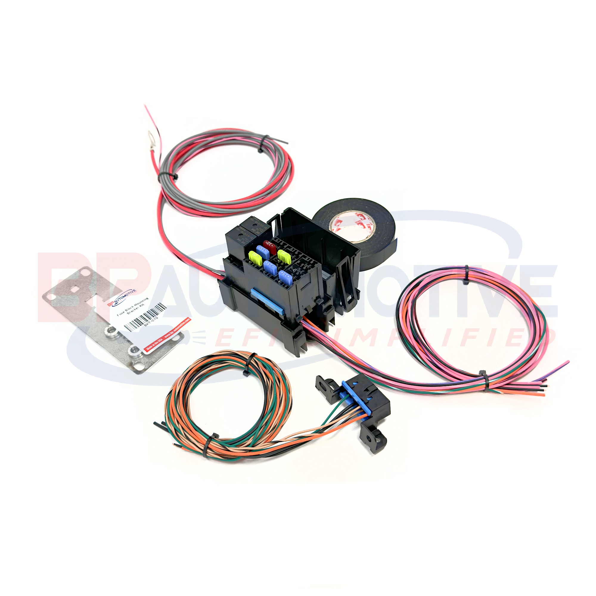 DIY Stand Alone Factory Harness Mod Kit
11. What is the Role of the PCM in the LS Swap OBD2 System?
The PCM (Powertrain Control Module) is a critical component in the LS swap OBD2 system. It serves as the central control unit for the engine and is responsible for communicating with the OBD2 port.
- Engine Control:
- The PCM monitors and controls various engine parameters, such as fuel injection, ignition timing, and air-fuel ratio, to optimize performance and efficiency.
- Data Transmission:
- The PCM transmits diagnostic data to the OBD2 port, allowing scan tools to retrieve diagnostic trouble codes (DTCs) and monitor engine performance.
- Sensor Monitoring:
- The PCM monitors signals from various sensors throughout the engine and vehicle, such as the MAF sensor, oxygen sensors, and coolant temperature sensor, to detect any issues.
- Actuator Control:
- The PCM controls various actuators, such as fuel injectors, ignition coils, and throttle position, to regulate engine operation.
- Communication with Other Modules:
- The PCM communicates with other modules in the vehicle, such as the transmission control module (TCM) and the anti-lock braking system (ABS), to coordinate vehicle functions.
12. How to Choose the Right OBD2 Connector for Your LS Swap?
Selecting the right OBD2 connector for your LS swap is crucial for ensuring compatibility and proper functionality. Here are some factors to consider when choosing an OBD2 connector.
- Compatibility:
- Ensure that the OBD2 connector is compatible with the PCM and the vehicle’s electrical system.
- Quality:
- Choose a high-quality OBD2 connector that is built to withstand the harsh conditions of the automotive environment.
- Pinout:
- Verify that the pinout of the OBD2 connector matches the wiring diagram for your LS swap.
- Terminals:
- Select an OBD2 connector that comes with high-quality terminals that are designed to securely connect to the wires.
- Ease of Installation:
- Choose an OBD2 connector that is easy to install and that comes with clear instructions.
- Durability:
- Look for an OBD2 connector that is made from durable materials that can withstand exposure to moisture, heat, and chemicals.
13. What Are the Benefits of Using a Pre-Made Fuse Block for LS Swap OBD2 Wiring?
Using a pre-made fuse block can greatly simplify the LS swap OBD2 wiring process and provide numerous benefits over building your own fuse block.
- Simplified Wiring:
- Pre-made fuse blocks come with pre-wired circuits for essential components, such as the PCM, injectors, coils, and transmission, reducing the amount of custom wiring required.
- Improved Reliability:
- Pre-made fuse blocks are built with high-quality components and construction techniques, resulting in improved reliability and performance.
- Ease of Installation:
- With pre-labeled and pre-terminated wires, a pre-made fuse block simplifies the installation process and saves time.
- Protection:
- Pre-made fuse blocks provide overcurrent protection for the OBD2 system and other electrical components, preventing damage from short circuits or overloads.
- Organization:
- A pre-made fuse block provides a centralized location for fuses and relays, making it easier to organize and manage the vehicle’s electrical system.
14. How Do You Integrate a Check Engine Light (MIL) into the LS Swap OBD2 System?
Integrating a Check Engine Light (MIL) into the LS swap OBD2 system is important for providing visual indication of diagnostic trouble codes (DTCs) and potential issues with the engine.
- Wiring the MIL:
- Connect the MIL wire from the PCM to an indicator light on the vehicle’s dashboard or instrument cluster.
- Selecting an Indicator Light:
- Choose an indicator light that is clearly visible and easily recognizable as the Check Engine Light.
- Testing the MIL:
- Verify that the MIL illuminates when a DTC is present in the PCM.
- Using a Standalone Harness:
- If you are using a standalone wiring harness, it may already include a pre-wired connection for the MIL.
- Custom Wiring:
- If you are custom wiring the MIL, consult the wiring diagram for your LS swap to determine the correct pin on the PCM to connect to the indicator light.
15. What is the Difference Between OBD1 and OBD2 Systems in Relation to LS Swaps?
Understanding the differences between OBD1 and OBD2 systems is important when performing an LS swap, as it can affect the wiring and diagnostic procedures.
- OBD1:
- OBD1 (On-Board Diagnostics I) was the first generation of on-board diagnostic systems, used in vehicles from the 1980s to the mid-1990s.
- OBD1 systems were less standardized than OBD2 systems, with different manufacturers using different connectors, protocols, and diagnostic codes.
- OBD1 systems typically provided less detailed diagnostic information than OBD2 systems.
- OBD2:
- OBD2 (On-Board Diagnostics II) is the second generation of on-board diagnostic systems, mandated in all vehicles sold in the United States since 1996.
- OBD2 systems are highly standardized, with a universal connector, protocol, and diagnostic codes.
- OBD2 systems provide more detailed diagnostic information than OBD1 systems, including real-time monitoring of engine parameters.
- LS Swaps:
- When performing an LS swap, it is generally recommended to use an OBD2 PCM and wiring harness, as this will provide more comprehensive diagnostic capabilities and ensure compliance with emissions testing regulations.
- If you are using an older LS engine with an OBD1 PCM, you may need to convert it to OBD2 in order to take advantage of the benefits of the OBD2 system.
16. Can You Use a Universal OBD2 Wiring Diagram for an LS Swap?
While a universal OBD2 wiring diagram can provide a general guideline, it is not recommended for an LS swap due to the specific wiring requirements of each engine and vehicle combination.
- Specificity:
- LS swaps involve unique wiring configurations that require a specific wiring diagram tailored to the engine and vehicle being used.
- Accuracy:
- A universal wiring diagram may not accurately reflect the pinouts and wiring requirements of your specific LS swap, leading to errors and potential damage.
- Reliability:
- Using a universal wiring diagram can result in unreliable connections and poor performance of the OBD2 system.
- Recommendation:
- It is always recommended to use a wiring diagram that is specifically designed for your LS swap to ensure accurate and reliable wiring.
17. How to Prepare Your Vehicle for the OBD2 Wiring Process?
Preparing your vehicle for the OBD2 wiring process is essential for ensuring a smooth and successful installation. Follow these steps to get your vehicle ready.
- Disconnect the Battery:
- Disconnect the negative terminal of the battery to prevent electrical shock and damage to the vehicle’s electrical system.
- Gather the Necessary Tools and Materials:
- Ensure that you have all the tools and materials needed for the wiring process, including the OBD2 connector, wiring harness, crimping tool, wire strippers, soldering iron, heat shrink tubing, and multimeter.
- Review the Wiring Diagram:
- Carefully review the wiring diagram for your LS swap to understand the pinouts, wiring requirements, and any additional notes or instructions.
- Identify the PCM Location:
- Locate the PCM in the vehicle and ensure that it is easily accessible for wiring.
- Prepare the Wiring Harness:
- Prepare the wiring harness by cutting the wires to the appropriate length and stripping the insulation from the ends.
- Label the Wires:
- Label each wire with its corresponding function to ensure accurate connections.
- Clean the Wiring Area:
- Clean the wiring area to remove any dirt, grease, or debris that could interfere with the wiring process.
18. What Should You Do After Completing the OBD2 Wiring?
After completing the OBD2 wiring, it is important to perform several checks and tests to ensure that the system is functioning correctly.
- Reconnect the Battery:
- Reconnect the negative terminal of the battery.
- Verify Connections:
- Double-check all wiring connections to ensure that they are secure and properly insulated.
- Test Continuity:
- Use a multimeter to test the continuity of the wires between the OBD2 connector and the PCM to ensure there are no breaks or shorts in the wiring.
- Check for Voltage:
- Verify that there is 12V+ power at pin 16 and a good ground connection at pins 4 and 5 of the OBD2 connector.
- Connect a Scan Tool:
- Connect a scan tool to the OBD2 port and verify that you can read diagnostic trouble codes (DTCs) and monitor engine parameters.
- Start the Engine:
- Start the engine and monitor its performance using the scan tool.
- Check for MIL Illumination:
- Verify that the Check Engine Light (MIL) illuminates when a DTC is present in the PCM.
- Test Drive the Vehicle:
- Take the vehicle for a test drive and monitor its performance using the scan tool.
19. How Do You Ensure Long-Term Reliability of the LS Swap OBD2 Wiring?
Ensuring the long-term reliability of the LS swap OBD2 wiring involves using high-quality materials, proper installation techniques, and regular maintenance.
- Use High-Quality Materials:
- Use automotive-grade wiring, connectors, and terminals that are designed to withstand the harsh conditions of the automotive environment.
- Proper Installation Techniques:
- Follow proper wiring techniques, such as crimping and soldering connections, to ensure secure and reliable connections.
- Protect the Wiring:
- Protect the wiring from abrasion, heat, and moisture by using wire loom, heat shrink tubing, and other protective materials.
- Regular Maintenance:
- Periodically inspect the wiring for any signs of damage or wear and replace any damaged components.
- Proper Grounding:
- Ensure that the ground connections are clean and secure to prevent corrosion and maintain a good electrical connection.
- Avoid Overloading Circuits:
- Avoid overloading circuits by using the appropriate fuse sizes and wiring gauges.
- Use a Fuse Block:
- Use a fuse block to provide overcurrent protection for the OBD2 system and other electrical components.
20. What Resources Can Help with LS Swap OBD2 Wiring?
Numerous resources can assist with LS swap OBD2 wiring, including online forums, wiring diagrams, and professional services.
- Online Forums:
- LS1Tech, PerformanceTrucks, and other online forums provide a wealth of information and support from experienced LS swap enthusiasts.
- Wiring Diagrams:
- Wiring diagrams for various LS engines and vehicle models can be found online or purchased from reputable sources.
- Standalone Harness Manufacturers:
- Companies like BP Automotive and Holley Performance offer standalone wiring harnesses that simplify the LS swap process.
- Professional Services:
- Qualified automotive technicians and LS swap specialists can provide expert assistance with wiring and troubleshooting.
- OBD2-SCANNER.EDU.VN:
- OBD2-SCANNER.EDU.VN offers comprehensive guides, resources, and services to help you with your LS swap OBD2 wiring needs.
Understanding and correctly implementing the LS swap OBD2 wiring diagram is crucial for a successful engine swap. By following the guidelines and best practices outlined in this comprehensive guide from OBD2-SCANNER.EDU.VN, you can ensure that your OBD2 port functions correctly, allowing for accurate diagnostics and compliance with emissions testing regulations.
Are you facing challenges with your LS swap OBD2 wiring? Contact us at OBD2-SCANNER.EDU.VN for expert guidance and solutions. Our team of experienced technicians is ready to assist you with all your diagnostic and repair needs. Reach out today via WhatsApp at +1 (641) 206-8880 or visit our location at 123 Main Street, Los Angeles, CA 90001, United States.