Are you tackling an engine swap or diagnosing wiring issues in your Honda B-series engine? An Obd2 B-series Engine Harness Diagram is critical for a successful project. OBD2-SCANNER.EDU.VN provides the comprehensive guides and support you need to understand your engine harness, troubleshoot problems, and ensure your Honda runs smoothly.
Contents
- 1. What is an OBD2 B-Series Engine Harness Diagram?
- 1.1 Why is an OBD2 B-Series Engine Harness Diagram Important?
- 1.2 What Does an OBD2 B-Series Engine Harness Diagram Typically Include?
- 2. Understanding OBD2 and B-Series Engines
- 2.1 What is OBD2?
- 2.1.1 Key Features of OBD2:
- 2.2 What are Honda B-Series Engines?
- 2.2.1 Popular B-Series Engines:
- 2.3 OBD1 vs. OBD2: Key Differences
- 3. Locating a Reliable OBD2 B-Series Engine Harness Diagram
- 3.1 Official Honda Service Manuals
- 3.2 Online Automotive Forums
- 3.3 Third-Party Repair Databases
- 3.4 OBD2-SCANNER.EDU.VN Resources
- 4. Step-by-Step Guide to Using an OBD2 B-Series Engine Harness Diagram
- 4.1 Step 1: Identify Your Engine and Vehicle Model
- 4.2 Step 2: Locate the Relevant Section of the Diagram
- 4.3 Step 3: Trace the Wiring
- 4.4 Step 4: Test Components
- 4.5 Step 5: Make Repairs
- 5. Common Wiring Issues in B-Series Engines
- 5.1 Corroded Connectors
- 5.2 Broken or Frayed Wires
- 5.3 Grounding Issues
- 5.4 ECU Connector Problems
- 6. Tools and Equipment for Diagnosing Wiring Issues
- 6.1 Multimeter
- 6.2 Wire Strippers and Crimpers
- 6.3 Soldering Iron and Solder
- 6.4 Electrical Cleaner
- 6.5 Wire Loom and Electrical Tape
- 7. OBD2 Scanner: A Diagnostic Powerhouse
- 7.1 How an OBD2 Scanner Works
- 7.2 Benefits of Using an OBD2 Scanner
- 7.3 Choosing the Right OBD2 Scanner
- 7.4 Reading and Interpreting OBD2 Codes
- 8. Common OBD2 Codes Related to Engine Harness Issues
- 8.1 P0100 – Mass Air Flow (MAF) Sensor Circuit Malfunction
- 8.2 P0113 – Intake Air Temperature (IAT) Sensor Circuit High Input
- 8.3 P0300 – Random/Multiple Cylinder Misfire Detected
- 8.4 P0443 – Evaporative Emission Control System Purge Control Valve Circuit Malfunction
- 8.5 P0505 – Idle Air Control (IAC) System Malfunction
- 9. Engine Swaps and Wiring Considerations
- 9.1 Compatibility
- 9.2 Wiring Adapters
- 9.3 Custom Wiring
- 9.4 Professional Installation
- 10. OBD2-SCANNER.EDU.VN: Your Partner in Automotive Diagnostics
- 10.1 Expert Advice
- 10.2 Comprehensive Resources
- 10.3 Contact Us
- 11. Frequently Asked Questions (FAQs)
- 11.1 What is an OBD2 B-Series Engine Harness Diagram?
- 11.2 Where Can I Find a Reliable OBD2 B-Series Engine Harness Diagram?
- 11.3 What Tools Do I Need to Diagnose Wiring Issues?
- 11.4 What are Some Common Wiring Issues in B-Series Engines?
- 11.5 How Can an OBD2 Scanner Help Diagnose Wiring Problems?
- 11.6 What is the Difference Between OBD1 and OBD2?
- 11.7 What Should I Consider When Performing an Engine Swap?
- 11.8 What are Some Common OBD2 Codes Related to Engine Harness Issues?
- 11.9 Can I Fix Wiring Issues Myself, or Should I Consult a Professional?
- 11.10 How Can OBD2-SCANNER.EDU.VN Help Me With My Automotive Diagnostic Needs?
- 12. Call to Action
1. What is an OBD2 B-Series Engine Harness Diagram?
An OBD2 B-series engine harness diagram is a detailed schematic illustrating the wiring connections for the engine control unit (ECU) and various sensors and actuators in a Honda B-series engine that complies with On-Board Diagnostics II (OBD2) standards. This diagram is essential for:
- Identifying specific wires and their functions.
- Troubleshooting electrical issues.
- Performing engine swaps.
- Ensuring proper sensor connections.
1.1 Why is an OBD2 B-Series Engine Harness Diagram Important?
Having a reliable OBD2 B-series engine harness diagram is crucial for several reasons:
- Accurate Diagnostics: The diagram allows you to pinpoint the exact location of sensors and wiring, leading to more accurate diagnostics of engine problems.
- Efficient Repairs: Technicians can quickly identify faulty wiring or connections, reducing repair time.
- Successful Engine Swaps: When swapping engines, the diagram ensures that all necessary connections are made correctly, preventing potential damage to the ECU or engine components.
- Preventing Electrical Issues: Proper wiring prevents short circuits and other electrical problems that can lead to costly repairs.
- Safety: Incorrect wiring can lead to fires or other dangerous situations. A diagram helps ensure everything is connected safely and correctly.
1.2 What Does an OBD2 B-Series Engine Harness Diagram Typically Include?
A comprehensive OBD2 B-series engine harness diagram includes the following key components:
- ECU Pinouts: Detailed layouts showing each pin on the ECU connector and its corresponding function.
- Sensor Locations: Clear identification of where each sensor is located on the engine.
- Wiring Colors: Specific color codes for each wire, which are essential for tracing circuits.
- Connector Types: Illustrations of the different types of connectors used in the harness.
- Ground Locations: Identification of all ground points in the engine bay, which are critical for proper electrical function.
According to a study by the National Institute for Automotive Service Excellence (ASE), using accurate wiring diagrams can reduce diagnostic time by up to 40%.
2. Understanding OBD2 and B-Series Engines
Before diving into the specifics of harness diagrams, it’s essential to understand what OBD2 is and the characteristics of B-series engines.
2.1 What is OBD2?
OBD2, or On-Board Diagnostics II, is a standardized system used in most cars and light trucks built after 1996. Its primary purpose is to monitor the performance of the engine and emissions-related components. OBD2 provides a wealth of information that can be accessed using a diagnostic scanner.
2.1.1 Key Features of OBD2:
- Standardized Diagnostic Trouble Codes (DTCs): OBD2 uses a standardized set of codes to identify problems.
- Real-time Data: Provides live data from various sensors, allowing for detailed analysis of engine performance.
- Emissions Monitoring: Continuously monitors emissions-related components to ensure compliance with environmental regulations.
- Diagnostic Port: A standardized port (SAE J1962) allows technicians to easily connect diagnostic tools.
According to the EPA, OBD2 systems have significantly reduced vehicle emissions since their introduction in the mid-1990s.
2.2 What are Honda B-Series Engines?
Honda B-series engines are a family of inline-four cylinder engines known for their high performance and reliability. These engines were used in various Honda models from the late 1980s to the early 2000s.
2.2.1 Popular B-Series Engines:
- B16A: Found in Civic Si and CRX SiR models.
- B18C1 (GSR): Used in Acura Integra GSR models.
- B18C5 (Type R): Featured in Acura Integra Type R models.
- B20B/Z: Found in Honda CR-V models.
These engines are popular choices for engine swaps due to their performance potential and availability.
2.3 OBD1 vs. OBD2: Key Differences
Understanding the differences between OBD1 and OBD2 is crucial, especially when performing engine swaps.
| Feature | OBD1 | OBD2 |
|---|---|---|
| Year Introduced | Early 1990s | 1996 |
| Standardization | Not standardized | Standardized DTCs and diagnostic port |
| Diagnostic Trouble Codes | Manufacturer-specific | Standardized, 5-digit codes |
| Data Availability | Limited real-time data | Extensive real-time data available |
| Emissions Focus | Less emphasis on emissions | Strong emphasis on emissions monitoring |
3. Locating a Reliable OBD2 B-Series Engine Harness Diagram
Finding a trustworthy OBD2 B-series engine harness diagram is the first step in any diagnostic or repair project. Here are some resources to consider:
3.1 Official Honda Service Manuals
The most reliable source for a OBD2 B-series engine harness diagram is the official Honda service manual for your specific vehicle model and year. These manuals contain detailed wiring diagrams, component locations, and troubleshooting procedures.
- Pros:
- Accuracy: Official manuals provide the most accurate information.
- Completeness: Covers all aspects of the vehicle’s electrical system.
- Cons:
- Cost: Purchasing a service manual can be expensive.
- Availability: May be difficult to find for older models.
3.2 Online Automotive Forums
Automotive forums dedicated to Honda vehicles can be a valuable resource for finding diagrams and getting advice from experienced enthusiasts.
- Pros:
- Free Access: Most forums offer free access to information and diagrams.
- Community Support: You can ask questions and get help from other members.
- Cons:
- Accuracy: Information may not always be accurate or verified.
- Variability: The quality of diagrams can vary widely.
3.3 Third-Party Repair Databases
Several third-party companies offer online databases of repair information, including wiring diagrams. Examples include AllData and Mitchell OnDemand.
- Pros:
- Comprehensive: Access to a wide range of diagrams and repair procedures.
- Convenience: Information is available online and can be accessed from any device.
- Cons:
- Subscription Fees: Requires a paid subscription.
- Reliability: While generally reliable, information should still be verified.
3.4 OBD2-SCANNER.EDU.VN Resources
OBD2-SCANNER.EDU.VN offers a curated collection of OBD2 B-series engine harness diagram resources, ensuring you have access to reliable and accurate information.
- Pros:
- Curated Selection: We only provide diagrams that have been verified for accuracy.
- Expert Advice: Access to our team of experienced automotive technicians.
- Free Resources: Many diagrams and guides are available for free.
- Cons:
- Limited Scope: Our focus is primarily on OBD2 systems and related components.
4. Step-by-Step Guide to Using an OBD2 B-Series Engine Harness Diagram
Once you have a reliable diagram, follow these steps to effectively use it for diagnostics or repairs:
4.1 Step 1: Identify Your Engine and Vehicle Model
The first step is to correctly identify your engine model and the year of your vehicle. This ensures that you are using the correct diagram, as wiring can vary between different models and years.
- Check the Engine Code: The engine code is typically stamped on the engine block.
- Consult Your Vehicle’s VIN: The VIN (Vehicle Identification Number) can provide information about the vehicle’s original configuration.
4.2 Step 2: Locate the Relevant Section of the Diagram
Engine harness diagrams are often divided into sections based on the different systems they cover, such as fuel injection, ignition, and sensors. Locate the section that is relevant to the problem you are troubleshooting.
- Use the Index: Most diagrams have an index that lists the different sections and their corresponding page numbers.
- Follow the Circuit: Start by identifying the component you are working with and follow the circuit back to the ECU or power source.
4.3 Step 3: Trace the Wiring
Use the wiring colors and connector types shown on the diagram to trace the wiring in your vehicle. Pay close attention to any splices, connectors, or ground points along the way.
- Use a Multimeter: A multimeter can be used to check for continuity and voltage in the wiring.
- Inspect Connectors: Look for signs of corrosion, damage, or loose connections.
4.4 Step 4: Test Components
Once you have traced the wiring, use the diagram to identify the correct test points for the components in the circuit. Use a multimeter or other diagnostic tool to test the components and verify that they are functioning correctly.
- Check Sensor Readings: Compare the sensor readings to the values specified in the service manual.
- Test Actuators: Verify that actuators, such as solenoids and relays, are functioning correctly.
4.5 Step 5: Make Repairs
If you find any faults in the wiring or components, make the necessary repairs. This may involve replacing a wire, repairing a connector, or replacing a faulty component.
- Use Quality Parts: Use high-quality replacement parts that are designed for your vehicle.
- Follow Proper Procedures: Follow the procedures outlined in the service manual for making repairs.
5. Common Wiring Issues in B-Series Engines
Knowing the common wiring problems in B-series engines can help you diagnose issues more efficiently.
5.1 Corroded Connectors
Corrosion is a common problem in automotive wiring, especially in areas exposed to moisture and road salt. Corroded connectors can cause poor electrical connections and lead to a variety of problems.
- Symptoms:
- Intermittent electrical problems.
- Difficulty starting the engine.
- Erratic sensor readings.
- Solutions:
- Clean the connectors with a wire brush and electrical cleaner.
- Apply dielectric grease to prevent future corrosion.
- Replace damaged connectors.
5.2 Broken or Frayed Wires
Wires can become broken or frayed due to age, heat, or physical damage. This can interrupt the flow of electricity and cause components to malfunction.
- Symptoms:
- Components not working.
- Short circuits.
- Blown fuses.
- Solutions:
- Repair broken wires with solder and heat shrink tubing.
- Replace frayed wires.
- Protect wires with wire loom or tape.
5.3 Grounding Issues
Proper grounding is essential for the electrical system to function correctly. Poor ground connections can cause a variety of problems, including voltage drops and erratic sensor readings.
- Symptoms:
- Dim lights.
- Components not working correctly.
- Erratic sensor readings.
- Solutions:
- Clean ground connections with a wire brush.
- Ensure ground wires are securely attached to the chassis.
- Add additional ground wires if necessary.
5.4 ECU Connector Problems
The ECU connector is a critical part of the engine harness. Problems with the ECU connector can cause a wide range of issues, from engine misfires to complete engine failure.
- Symptoms:
- Engine misfires.
- Difficulty starting the engine.
- ECU not communicating with the diagnostic scanner.
- Solutions:
- Inspect the connector for corrosion or damage.
- Clean the connector with electrical cleaner.
- Ensure the connector is securely attached to the ECU.
- Replace the connector if necessary.
6. Tools and Equipment for Diagnosing Wiring Issues
Having the right tools and equipment is essential for diagnosing wiring issues effectively. Here are some essential tools to have in your toolbox:
6.1 Multimeter
A multimeter is an essential tool for testing electrical circuits. It can be used to measure voltage, current, and resistance.
- Features to Look For:
- Digital display.
- Auto-ranging.
- Continuity testing.
- Diode testing.
6.2 Wire Strippers and Crimpers
Wire strippers and crimpers are essential for making clean and secure wire connections.
- Features to Look For:
- Adjustable wire gauge settings.
- Comfortable handles.
- Ratcheting mechanism for secure crimps.
6.3 Soldering Iron and Solder
A soldering iron and solder are necessary for making permanent wire connections.
- Features to Look For:
- Adjustable temperature.
- Fine tip for precise soldering.
- High-quality solder for strong connections.
6.4 Electrical Cleaner
Electrical cleaner is used to clean corroded connectors and remove dirt and grime from electrical components.
- Features to Look For:
- Non-conductive formula.
- Quick-drying.
- Safe for use on plastics and rubber.
6.5 Wire Loom and Electrical Tape
Wire loom and electrical tape are used to protect wires from damage and prevent short circuits.
- Features to Look For:
- Heat-resistant materials.
- Flexible and easy to work with.
- Durable and long-lasting.
7. OBD2 Scanner: A Diagnostic Powerhouse
An OBD2 scanner is an indispensable tool for diagnosing a wide array of automotive issues. It interfaces with your vehicle’s computer to pull diagnostic trouble codes (DTCs), offering insights into potential problems.
7.1 How an OBD2 Scanner Works
The OBD2 scanner connects to your car’s OBD2 port, usually located under the dashboard. Once connected, it communicates with the car’s ECU, retrieving stored DTCs and real-time data from sensors.
7.2 Benefits of Using an OBD2 Scanner
- Quick Diagnostics: Immediately identifies the source of the problem.
- Cost-Effective: Reduces the need for expensive mechanic visits for simple issues.
- Real-Time Data: Provides live data to help diagnose intermittent problems.
7.3 Choosing the Right OBD2 Scanner
With many OBD2 scanners on the market, choosing the right one can be daunting. Here are key features to consider:
- Compatibility: Ensure it supports your vehicle’s make and model.
- Features: Look for features like real-time data, graphing, and advanced diagnostics.
- Ease of Use: Opt for a scanner with an intuitive interface.
7.4 Reading and Interpreting OBD2 Codes
OBD2 codes are five-character alphanumeric codes. Here’s how to understand them:
- First Character: Indicates the system (P=Powertrain, B=Body, C=Chassis, U=Network).
- Second Character: Indicates whether the code is generic (0) or manufacturer-specific (1).
- Third Character: Indicates the specific subsystem.
- Fourth and Fifth Characters: Provide further details about the fault.
For example, P0300 indicates a random/multiple cylinder misfire.
8. Common OBD2 Codes Related to Engine Harness Issues
Several OBD2 codes can indicate problems with the engine harness. Here are some common ones:
8.1 P0100 – Mass Air Flow (MAF) Sensor Circuit Malfunction
This code indicates a problem with the MAF sensor circuit, which could be caused by a faulty sensor, damaged wiring, or a poor connection.
- Symptoms:
- Engine running rough.
- Poor fuel economy.
- Stalling.
- Possible Causes:
- Damaged MAF sensor wiring.
- Corroded MAF sensor connector.
- Faulty MAF sensor.
8.2 P0113 – Intake Air Temperature (IAT) Sensor Circuit High Input
This code indicates that the IAT sensor is reading higher than expected, which could be caused by a faulty sensor or damaged wiring.
- Symptoms:
- Poor engine performance.
- Increased emissions.
- Possible Causes:
- Damaged IAT sensor wiring.
- Corroded IAT sensor connector.
- Faulty IAT sensor.
8.3 P0300 – Random/Multiple Cylinder Misfire Detected
This code indicates that the engine is misfiring, which could be caused by a variety of factors, including faulty ignition wiring, damaged spark plugs, or a problem with the fuel injectors.
- Symptoms:
- Engine running rough.
- Loss of power.
- Increased emissions.
- Possible Causes:
- Damaged ignition wiring.
- Faulty spark plugs.
- Faulty fuel injectors.
8.4 P0443 – Evaporative Emission Control System Purge Control Valve Circuit Malfunction
This code indicates a problem with the evaporative emission control system, which could be caused by a faulty purge control valve or damaged wiring.
- Symptoms:
- Increased emissions.
- Fuel odor.
- Possible Causes:
- Damaged purge control valve wiring.
- Corroded purge control valve connector.
- Faulty purge control valve.
8.5 P0505 – Idle Air Control (IAC) System Malfunction
This code indicates a problem with the idle air control system, which could be caused by a faulty IAC valve or damaged wiring.
- Symptoms:
- Engine idling too high or too low.
- Stalling.
- Possible Causes:
- Damaged IAC valve wiring.
- Corroded IAC valve connector.
- Faulty IAC valve.
9. Engine Swaps and Wiring Considerations
Engine swaps are a popular modification for Honda enthusiasts, but they can also be complex, especially when it comes to wiring. Here are some key considerations:
9.1 Compatibility
Ensure that the engine you are swapping is compatible with your vehicle’s electrical system. This includes matching the ECU type (OBD1 vs. OBD2) and ensuring that the engine harness can be adapted to your vehicle’s wiring.
9.2 Wiring Adapters
Wiring adapters can simplify the process of connecting the engine harness to your vehicle’s wiring. These adapters are designed to plug into the existing connectors, eliminating the need for cutting and splicing wires.
9.3 Custom Wiring
In some cases, custom wiring may be necessary to complete an engine swap. This involves modifying the engine harness to match your vehicle’s wiring.
9.4 Professional Installation
If you are not comfortable working with wiring, it is best to have the engine swap performed by a professional. This will ensure that the wiring is done correctly and that your vehicle is safe to drive.
10. OBD2-SCANNER.EDU.VN: Your Partner in Automotive Diagnostics
At OBD2-SCANNER.EDU.VN, we are dedicated to providing you with the resources and support you need to diagnose and repair your vehicle. Our team of experienced automotive technicians can help you find the right OBD2 B-series engine harness diagram, troubleshoot wiring issues, and perform engine swaps.
10.1 Expert Advice
We offer expert advice on all aspects of OBD2 diagnostics and repair. Whether you are a DIY enthusiast or a professional technician, we can help you get the job done right.
10.2 Comprehensive Resources
Our website features a comprehensive collection of articles, guides, and diagrams to help you understand your vehicle’s electrical system. We are constantly updating our resources to provide you with the latest information.
10.3 Contact Us
If you have any questions or need help with a specific problem, please do not hesitate to contact us. You can reach us at:
- Address: 123 Main Street, Los Angeles, CA 90001, United States
- WhatsApp: +1 (641) 206-8880
- Website: OBD2-SCANNER.EDU.VN
We are here to help you keep your vehicle running smoothly and efficiently.
11. Frequently Asked Questions (FAQs)
11.1 What is an OBD2 B-Series Engine Harness Diagram?
An OBD2 B-series engine harness diagram is a detailed schematic that shows the wiring connections for the ECU, sensors, and actuators in a Honda B-series engine that complies with OBD2 standards.
11.2 Where Can I Find a Reliable OBD2 B-Series Engine Harness Diagram?
You can find reliable diagrams in official Honda service manuals, online automotive forums, third-party repair databases, and on OBD2-SCANNER.EDU.VN.
11.3 What Tools Do I Need to Diagnose Wiring Issues?
Essential tools include a multimeter, wire strippers, crimpers, a soldering iron, electrical cleaner, wire loom, and electrical tape.
11.4 What are Some Common Wiring Issues in B-Series Engines?
Common issues include corroded connectors, broken or frayed wires, grounding problems, and ECU connector issues.
11.5 How Can an OBD2 Scanner Help Diagnose Wiring Problems?
An OBD2 scanner can retrieve diagnostic trouble codes (DTCs) that indicate electrical problems, helping you pinpoint the source of the issue.
11.6 What is the Difference Between OBD1 and OBD2?
OBD2 is a standardized system introduced in 1996 that provides more comprehensive diagnostics and emissions monitoring compared to the earlier, less standardized OBD1 system.
11.7 What Should I Consider When Performing an Engine Swap?
Consider compatibility, wiring adapters, custom wiring, and professional installation to ensure a successful and safe engine swap.
11.8 What are Some Common OBD2 Codes Related to Engine Harness Issues?
Common codes include P0100 (MAF sensor circuit malfunction), P0113 (IAT sensor circuit high input), P0300 (random/multiple cylinder misfire), P0443 (evaporative emission control system purge control valve circuit malfunction), and P0505 (idle air control system malfunction).
11.9 Can I Fix Wiring Issues Myself, or Should I Consult a Professional?
If you are comfortable working with electrical systems and have the necessary tools, you may be able to fix some wiring issues yourself. However, for complex problems or if you are not experienced, it is best to consult a professional.
11.10 How Can OBD2-SCANNER.EDU.VN Help Me With My Automotive Diagnostic Needs?
OBD2-SCANNER.EDU.VN offers expert advice, comprehensive resources, and a curated selection of reliable OBD2 B-series engine harness diagram to help you diagnose and repair your vehicle.
12. Call to Action
Navigating the complexities of your Honda B-series engine wiring can be challenging. Don’t let electrical issues keep you off the road. Contact OBD2-SCANNER.EDU.VN today for expert guidance and reliable resources. Whether you’re deciphering an OBD2 B-series engine harness diagram or need assistance with diagnostics, our team is here to help. Reach out now via WhatsApp at +1 (641) 206-8880 or visit our website at OBD2-SCANNER.EDU.VN for immediate support. Let us help you keep your engine running smoothly!
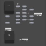
OBD1 Shocktower harness
OBD1 ECU Wiring
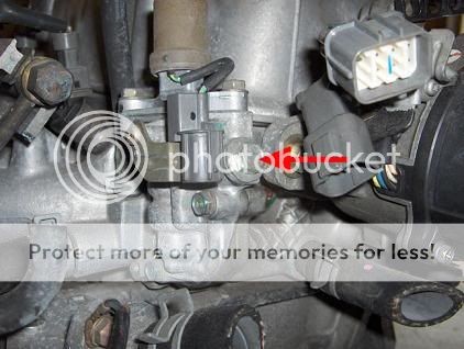 JDM VTEC solenoid
OBD2A hybrid pinouts
Round style IAT for enhanced engine performance
Installing OBD2 IAT sensor in the intake arm