The Obd2 Communication Protocol is your car’s standardized language for self-diagnosis, enabling the extraction of diagnostic trouble codes (DTCs) and real-time data via the OBD2 connector. At OBD2-SCANNER.EDU.VN, we provide comprehensive resources to help you understand and utilize this protocol effectively for vehicle diagnostics and repair. This guide covers everything from the basics of OBD2 to advanced logging and decoding techniques, enhancing your automotive diagnostic capabilities, and offering insights into automotive diagnostics, vehicle communication protocols, and automotive data analysis.
Contents
- 1. What is OBD2 Communication Protocol?
- 1.1. Key Aspects of OBD2 Protocol
- 1.2. Benefits of Understanding OBD2 Communication Protocol
- 2. Which Cars Support OBD2?
- 2.1. Identifying OBD2 Compliance
- 2.2. Exceptions and Considerations
- 3. What Is The History Of OBD2?
- 3.1. OBD3 and Telematics
- 3.2. Challenges and Concerns
- 3.3. Industry Perspectives
- 4. What Are OBD2 Standards?
- 4.1. SAE J1962: The OBD2 Connector Standard
- 4.2. ISO 15765-4: OBD2 and CAN Bus
- 4.3. SAE J1979 and ISO 15031-5: OBD2 Diagnostic Services
- 4.4. ISO 15765-2: Transporting OBD2 Messages via ISO-TP
- 5. How Does OBD2 Work With CAN Bus?
- 5.1. CAN Bus Basics
- 5.2. OBD2 and CAN Integration
- 5.3. CAN Identifiers
- 5.4. Validating Bit-Rate and CAN ID
- 6. How Is An OBD2 Message Structured?
- 6.1. Understanding the Message Components
- 6.2. OBD2 Modes and PIDs
- 6.3. Example: Requesting Vehicle Speed
- 7. How Do You Log and Decode OBD2 Data?
- 7.1. Step 1: Test Bit-Rate, IDs & Supported PIDs
- 7.2. Step 2: Configure OBD2 PID Requests
- 7.3. Step 3: DBC Decode Raw OBD2 Data
- 8. What Are Multi-Frame OBD2 Examples Using ISO-TP?
- 8.1. OBD2 Vehicle Identification Number (VIN)
- 8.2. OBD2 Multi-PID Request (6x)
- 8.3. OBD2 Diagnostic Trouble Codes (DTCs)
- 9. What Are Use Cases For OBD2 Data Logging?
- 9.1. Logging Data from Cars
- 9.2. Real-Time Car Diagnostics
- 9.3. Predictive Maintenance
- 9.4. Vehicle Blackbox Logger
- 10. FAQ About OBD2 Communication Protocol
- 10.1. What is an OBD2 Scanner?
- 10.2. How Do I Read OBD2 Codes?
- 10.3. What Are Common OBD2 Codes and Their Meanings?
1. What is OBD2 Communication Protocol?
The OBD2 communication protocol is a standardized system that allows automotive technicians and enthusiasts to access data from a vehicle’s onboard computer. It is the language that diagnostic tools use to communicate with the car’s computer, retrieve diagnostic trouble codes (DTCs), and monitor real-time data. This protocol ensures consistency across different vehicle makes and models, making it easier to diagnose and repair issues.
OBD2 is your car’s built-in self-diagnostic system. It is a standardized protocol that allows extraction of diagnostic trouble codes (DTCs) and real-time data via the OBD2 connector. You’ve probably encountered OBD2 already: Ever noticed the malfunction indicator light on your dashboard? That is your car telling you there is an issue. If you visit a mechanic, he will use an OBD2 scanner to diagnose the issue. To do so, he will connect the OBD2 reader to the OBD2 16 pin connector near the steering wheel. The tool sends ‘OBD2 requests’ to the car and the car responds with ‘OBD2 responses’ that can contain e.g. speed, fuel level or Diagnostic Trouble Codes (DTCs) – making it possible to troubleshoot issues faster.
1.1. Key Aspects of OBD2 Protocol
The OBD2 protocol involves several key aspects that are crucial for effective vehicle diagnostics. Here are some of the most important components:
- Diagnostic Trouble Codes (DTCs): These are codes stored in the vehicle’s computer that indicate a specific problem. For example, a DTC might indicate a faulty oxygen sensor or a misfiring engine.
- Real-Time Data: The protocol allows access to real-time data such as engine speed (RPM), vehicle speed, coolant temperature, and fuel consumption. This data helps in monitoring the vehicle’s performance and diagnosing issues as they occur.
- OBD2 Connector: This is a standardized 16-pin connector located in the vehicle, typically under the dashboard. Diagnostic tools connect to this port to communicate with the vehicle’s computer.
- Communication Protocols: OBD2 uses various communication protocols, including CAN (Controller Area Network), ISO 9141-2, and SAE J1850. These protocols define how data is transmitted between the diagnostic tool and the vehicle.
1.2. Benefits of Understanding OBD2 Communication Protocol
Understanding the OBD2 communication protocol offers numerous benefits for both professional technicians and vehicle owners:
- Accurate Diagnostics: By understanding how to interpret DTCs and real-time data, you can accurately diagnose vehicle problems and identify the root cause of issues.
- Cost Savings: Accurate diagnostics can lead to more efficient repairs, saving time and money. You can avoid unnecessary repairs by pinpointing the exact problem.
- Improved Vehicle Performance: Monitoring real-time data helps in identifying performance issues early, allowing for timely maintenance and preventing more significant problems.
- DIY Repairs: With a solid understanding of the OBD2 protocol, you can perform many basic repairs yourself, reducing your reliance on expensive garage services.
- Better Communication with Mechanics: Being knowledgeable about your vehicle’s diagnostics enables better communication with mechanics, ensuring you understand the proposed repairs and can make informed decisions.
2. Which Cars Support OBD2?
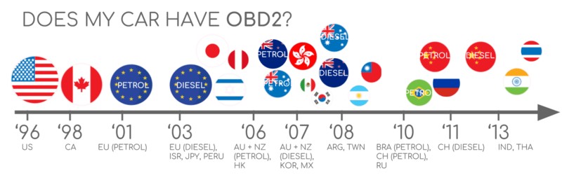
In short: Probably! Almost all newer non-electric cars support OBD2 and most run on CAN bus. For older cars, note that even if a 16 pin OBD2 connector is present, it may still not support OBD2. One way to determine compliance is to see where & when it was bought new:
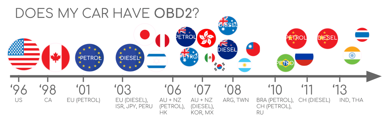 Does My Car Have OBD2?
OBD2 was mandated in the United States for all cars and light trucks manufactured after 1996. In Europe, OBD2 (also known as EOBD) became mandatory for gasoline cars in 2001 and diesel cars in 2003. This standardization ensures that vehicles can be diagnosed using any compatible OBD2 scanner, regardless of the manufacturer.
2.1. Identifying OBD2 Compliance
Determining whether your car supports OBD2 is generally straightforward:
- Check the Manufacturing Year: If your car was manufactured in 1996 or later in the United States, it is almost certainly OBD2 compliant. In Europe, check if it’s a gasoline car from 2001 onwards or a diesel car from 2003 onwards.
- Locate the OBD2 Port: Look for the 16-pin OBD2 connector, usually located under the dashboard, near the steering wheel. The presence of this port indicates OBD2 support.
- Consult the Vehicle Manual: The owner’s manual should explicitly state whether the vehicle is OBD2 compliant.
- Check for OBD Compliance Stickers: Some vehicles have stickers indicating OBD2 compliance, usually found under the hood or on the door frame.
2.2. Exceptions and Considerations
While most vehicles adhere to the OBD2 standard, there are some exceptions and considerations to keep in mind:
- Electric Vehicles (EVs): Many electric vehicles do not fully support the standard OBD2 protocol. Instead, they often use OEM-specific protocols for diagnostics.
- Hybrid Vehicles: Hybrid vehicles typically support OBD2, but they may also have additional proprietary diagnostic systems.
- Pre-1996 Vehicles: Vehicles manufactured before 1996 in the US may use the older OBD1 standard, which is not compatible with OBD2 scanners.
- Grey Market Vehicles: Imported vehicles not originally intended for sale in the US or Europe may not comply with OBD2 standards.
3. What Is The History Of OBD2?
OBD2 originates from California where the California Air Resources Board (CARB) required OBD in all new cars from 1991+ for emission control purposes.
The OBD2 standard was recommended by the Society of Automotive Engineers (SAE) and standardized DTCs and the OBD connector across manufacturers (SAE J1962).
From there, the OBD2 standard was rolled out step-by-step:
- 1996: OBD2 made mandatory in USA for cars/light trucks
- 2001: Required in EU for gasoline cars
- 2003: Required in EU also for diesel cars (EOBD)
- 2005: OBD2 was required in US for medium duty vehicles
- 2008: US cars must use ISO 15765-4 (CAN) as OBD2 basis
- 2010: Finally, OBD2 was required in US heavy duty vehicles
3.1. OBD3 and Telematics
The future of OBD may involve OBD3, which aims to add telematics to all cars. This would involve integrating a small radio transponder (similar to those used in bridge tolls) into vehicles. This transponder would transmit the vehicle’s identification number (VIN) and DTCs via WiFi to a central server for monitoring. This approach could streamline emission control checks and offer real-time diagnostics.
3.2. Challenges and Concerns
Despite the potential benefits, the implementation of OBD3 raises several challenges and concerns. Privacy issues are paramount, as continuous monitoring of vehicle data could lead to surveillance. There are also concerns about who controls the data and how it is used.
3.3. Industry Perspectives
The automotive industry has differing views on the future of OBD. Some manufacturers propose restricting third-party access to OBD2 data while driving, collecting data on a central server instead. This move would give manufacturers greater control over automotive data, potentially creating a data-driven economy.
4. What Are OBD2 Standards?
Onboard diagnostics, OBD2, is a higher layer protocol (like a language). CAN is a method for communication (like a phone). This makes OBD2 comparable to other CAN based higher-layer protocols like J1939, CANopen and NMEA 2000.
In particular, the OBD2 standards specify the OBD2 connector, lower-layer protocols, OBD2 parameter IDs (PID) and more.
The standards can be displayed in a 7-layer OSI model – and in the next sections we focus on the most important ones.
In the OSI model overview, you may note that several layers are covered by both SAE and ISO standards. Generally, this reflects standards for OBD defined in USA (SAE) and EU (ISO). Several standards are almost technically equivalent, for example SAE J1979 vs. ISO 15031-5 and SAE J1962 vs. ISO 15031-3.
4.1. SAE J1962: The OBD2 Connector Standard
The SAE J1962 standard specifies the physical OBD2 connector, a 16-pin Data Link Connector (DLC) used to access vehicle data. This standard ensures that all OBD2-compliant vehicles have a uniform connector, simplifying the process of connecting diagnostic tools.
Key Features of the SAE J1962 Standard:
- Pin Assignments: The standard defines the specific function of each of the 16 pins, including power, ground, and communication lines.
- Connector Type: Specifies the physical dimensions and materials of the connector to ensure compatibility across different vehicles and diagnostic tools.
- Voltage Requirements: The standard also outlines the voltage requirements for the connector, ensuring that diagnostic tools operate safely and effectively.
4.2. ISO 15765-4: OBD2 and CAN Bus
Since 2008, CAN bus has been the mandatory lower-layer protocol for OBD2 in all cars sold in the US as per ISO 15765.
ISO 15765-4 (aka Diagnostics over CAN or DoCAN) refers to a set of restrictions applied to the CAN standard (ISO 11898).
Specifically, it standardizes the CAN interface for test equipment with focus on the physical, data link and network layer:
- The CAN bus bit-rate must be either 250K or 500K
- The CAN IDs can be 11-bit or 29-bit
- Specific CAN IDs are used for OBD requests/responses
- The diagnostic CAN frame data length must be 8 bytes
- The OBD2 adapter cable must be max 5 meters
4.3. SAE J1979 and ISO 15031-5: OBD2 Diagnostic Services
The SAE J1979 and ISO 15031-5 standards define the diagnostic services (or modes) available through OBD2. These services allow diagnostic tools to request and receive information from the vehicle’s computer.
Key Diagnostic Services:
- Mode 01: Displays current real-time data such as engine speed, vehicle speed, and coolant temperature.
- Mode 02: Displays freeze frame data, which is a snapshot of data captured when a DTC is set.
- Mode 03: Displays stored Diagnostic Trouble Codes (DTCs) related to emissions.
- Mode 04: Clears stored DTCs and resets the malfunction indicator light (MIL).
- Mode 05: Tests oxygen sensors.
- Mode 06: Tests non-continuously monitored systems.
- Mode 07: Displays pending DTCs detected during the current or last driving cycle.
- Mode 08: Controls on-board systems, such as evaporative emission control systems.
- Mode 09: Requests vehicle information, such as the Vehicle Identification Number (VIN).
- Mode 0A: Displays permanent DTCs that cannot be cleared by disconnecting the battery or using a scan tool.
4.4. ISO 15765-2: Transporting OBD2 Messages via ISO-TP
All OBD2 data is communicated on the CAN bus through a transport protocol called ISO-TP (ISO 15765-2). This enables communication of payloads that exceed 8 bytes. This is necessary in OBD2 e.g. when extracting the Vehicle Identification Number (VIN) or Diagnostic Trouble Codes (DTCs). Here, ISO 15765-2 enables segmentation, flow control and reassembly.
5. How Does OBD2 Work With CAN Bus?
The OBD2 system relies heavily on the Controller Area Network (CAN) bus for communication. CAN bus is a robust communication protocol that allows various electronic control units (ECUs) within the vehicle to communicate with each other without a central host computer.
5.1. CAN Bus Basics
CAN bus operates on a two-wire system, CAN High (CANH) and CAN Low (CANL), allowing data transmission rates of up to 1 Mbps. The protocol is designed to be highly reliable and is used for critical vehicle functions such as engine management, transmission control, and anti-lock braking systems.
5.2. OBD2 and CAN Integration
In OBD2 systems, the diagnostic tool connects to the vehicle’s CAN bus through the OBD2 connector. The tool sends requests to the ECUs, and the ECUs respond with the requested data or diagnostic information. The CAN bus ensures that these communications are reliable and efficient.
5.3. CAN Identifiers
All OBD2 communication involves request / response messages. In most cars, 11-bit CAN IDs are used for OBD2 communication. Here, the ‘Functional Addressing’ ID is 0x7DF, which corresponds to asking all OBD2 compatible ECUs if they have data to report on the requested parameter (see ISO 15765-4). In contrast, CAN IDs 0x7E0-0x7E7 can be used to perform ‘Physical Addressing’ requests from specific ECUs (less commonly used).
ECUs can respond with 11-bit IDs 0x7E8-0x7EF. The most common response ID is 0x7E8 (ECM, Engine Control Module) and to some extent 0x7E9 (TCM, Transmission Control Module).
In some vehicles (e.g. vans and light/medium/heavy duty vehicles), you may find that OBD2 communication uses extended 29-bit CAN identifiers instead of 11-bit CAN identifiers.
Here, the ‘Functional Addressing’ CAN ID is 0x18DB33F1.
If the vehicle responds, you will see responses with CAN IDs 0x18DAF100 to 0x18DAF1FF (typically 18DAF110 and 18DAF11E). The response ID is also sometimes shown in the ‘J1939 PGN’ form, specifically the PGN 0xDA00 (55808), which in the J1939-71 standard is marked as ‘Reserved for ISO 15765-2’.
5.4. Validating Bit-Rate and CAN ID
As explained, OBD2 may use one of two bit-rates (250K, 500K) and one of two CAN ID lengths (11-bit, 29-bit). This results in 4 potential combinations. In modern cars, 500K and 11-bit IDs is the most common one – but external tools should verify this in a systematic way.
ISO 15765-4 provides recommendations for how to perform a systematic initialization sequence to determine the relevant combination, which we illustrate in the flowchart. The method leverages that OBD2 compliant vehicles must respond to a specific mandatory OBD2 request (see the OBD2 PID section for details) – and the fact that transmitting data with an incorrect bit-rate will cause CAN error frames.
6. How Is An OBD2 Message Structured?
To better understand OBD2 on CAN, let us consider a raw ‘Single Frame’ OBD2 CAN message. In simplified terms, an OBD2 message is comprised of an identifier, data length (PCI field) and data. The data is split in Mode, parameter ID (PID) and data bytes.
6.1. Understanding the Message Components
An OBD2 message is composed of several key components, each playing a crucial role in data transmission and interpretation. These components include the message identifier, data length, mode, Parameter ID (PID), and data bytes.
- Message Identifier: This is the CAN ID used to identify the source and destination of the message. For example, 0x7DF is a functional addressing ID used to ask all OBD2-compatible ECUs for data.
- Data Length (PCI Field): This field specifies the length of the data being transmitted. In single-frame messages, the first byte indicates the payload length, leaving the remaining bytes for OBD2-related communication.
- Mode: This indicates the type of diagnostic service being requested or provided. Common modes include 0x01 for real-time data and 0x03 for diagnostic trouble codes.
- Parameter ID (PID): Each mode contains parameter IDs that specify the particular data being requested or reported, such as vehicle speed or engine RPM.
- Data Bytes: These bytes contain the actual data being transmitted. The interpretation of these bytes depends on the mode and PID being used.
6.2. OBD2 Modes and PIDs
There are 10 OBD2 diagnostic services (or modes). Mode 0x01 shows current real-time data, while others are used to show/clear diagnostic trouble codes (DTCs) or show freeze frame data.
Vehicles do not have to support all OBD2 modes – and they may support modes outside the 10 standardized modes (aka OEM-specific OBD2 modes).
In OBD2 messages, the mode is in the 2nd byte. In the request, the mode is included directly (e.g. 0x01), while in the response 0x40 is added to the mode (e.g. resulting in 0x41).
Each OBD2 mode contains parameter IDs (PIDs). As an example, mode 0x01 contains ~200 standardized PIDs with real-time data on e.g. speed, RPM and fuel level. However, a vehicle does not have to support all OBD2 PIDs in a mode. In practice, most vehicles only support a small subset.
Specifically, if an emissions-related ECU supports any OBD2 services, then it must support mode 0x01 PID 0x00. In response to this PID, the vehicle ECU informs whether it supports PIDs 0x01-0x20. This makes PID 0x00 useful as a fundamental ‘OBD2 compatibility test’. Further, PIDs 0x20, 0x40, …, 0xC0 can be used to determine the support for the remaining mode 0x01 PIDs.
6.3. Example: Requesting Vehicle Speed
Consider an example of requesting and receiving vehicle speed data.
- Request: An external tool sends a request message to the car with CAN ID 0x7DF, containing two payload bytes: Mode 0x01 and PID 0x0D (vehicle speed).
- Response: The car responds via CAN ID 0x7E8, containing three payload bytes, including the vehicle speed value in the fourth byte, 0x32 (50 in decimal form).
By looking up the decoding rules for OBD2 PID 0x0D, you determine that the physical value is 50 km/h.
7. How Do You Log and Decode OBD2 Data?
In this section we provide a practical example of how you can log OBD2 data with the CANedge CAN bus data logger.
The CANedge lets you configure custom CAN frames to be transmitted which allows it to be used for e.g. OBD2 logging.
Once configured, the device can be easily connected to your vehicle via our OBD2-DB9 adapter cable.
7.1. Step 1: Test Bit-Rate, IDs & Supported PIDs
As discussed, ISO 15765-4 describes how to determine which bit-rate and IDs are used by a specific vehicle. You can test this with the CANedge as below (see the CANedge Intro for details):
- Send CAN frame at 500K and check if successful (else try 250K).
- Use the identified bit-rate for subsequent communication.
- Send multiple ‘Supported PIDs’ requests and review the results.
- Based on response IDs you can determine 11-bit vs. 29-bit.
- Based on response data you can see what PIDs are supported.
Most 2008+ non-EV cars support 40-80 PIDs via 500K bit-rate, 11-bit CAN IDs and the OBD2/OBDonEDS protocol.
As exemplified in the asammdf GUI screenshot, it is common to see multiple responses to a single OBD request. This is because we use the 0x7DF request ID, which polls all ECUs for a response. Since all OBD2/OBDonEDS-compliant ECUs must support service 0x01 PID 0x00, there are often many responses to this PID in particular. As evident, for subsequent ‘Supported PIDs’ requests there are gradually fewer ECUs that respond. Note also that the ECM ECU (0x7E8) itself supports all the PIDs that are supported by other ECUs in this example, meaning the busload may be reduced by only asking specifically this ECU for responses by changing to the ‘Physical Addressing’ CAN ID 0x7E0 for subsequent communication.
 OBD2 bit rate test
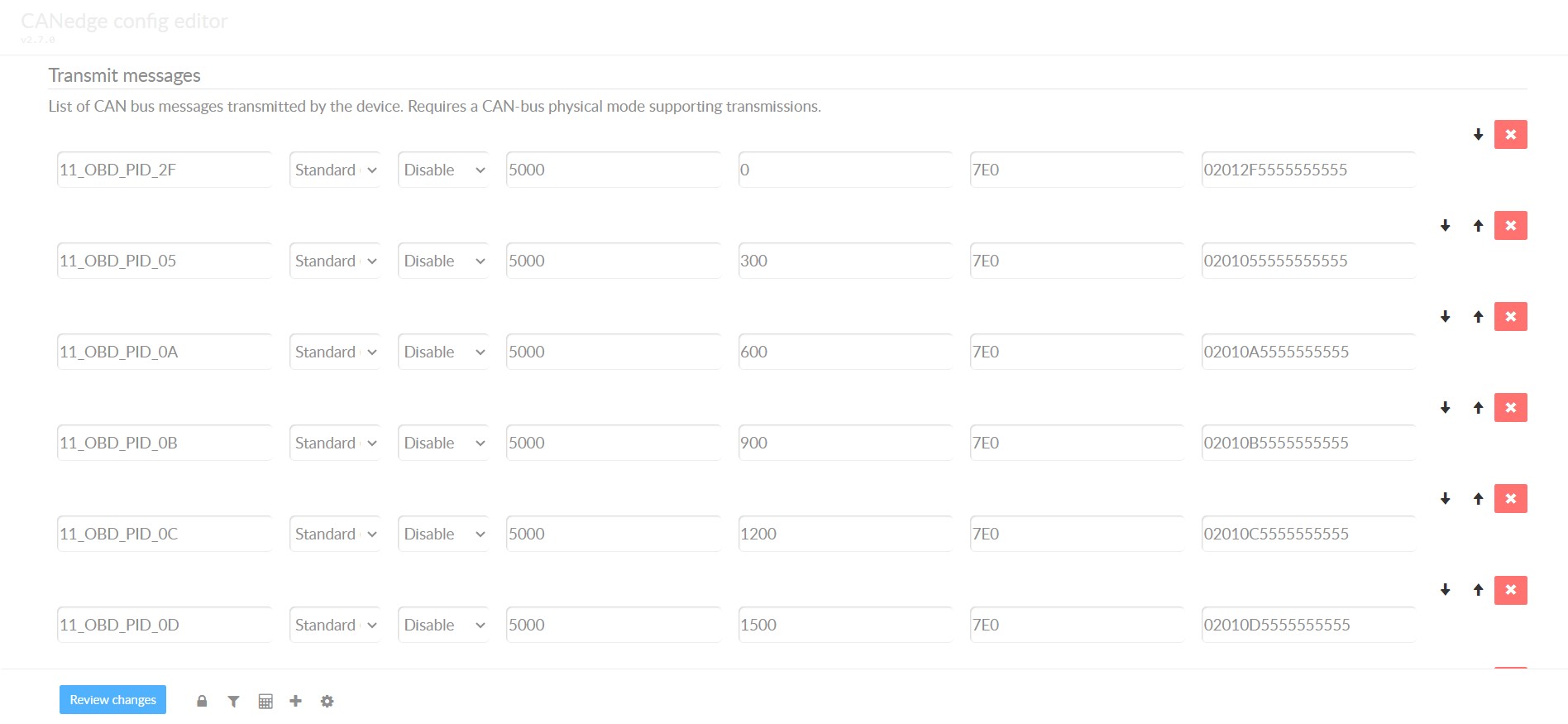
7.2. Step 2: Configure OBD2 PID Requests
You now know which OBD2 PIDs are supported by your vehicle – and what bit-rate and CAN IDs to use when requesting them.
Next, you configure your transmit list with PIDs of interest.
A few things to consider:
- CAN IDs: Shift to ‘Physical Addressing’ request IDs (e.g. 0x7E0) to avoid multiple responses to each request.
- Spacing: Add 300-500 ms between each OBD2 request (spamming the ECUs may cause them to not respond).
- Battery drain: Use triggers to stop transmitting when the vehicle is inactive (to avoid ‘waking up’ ECUs).
- Filters: Add filters to only record OBD2 responses (e.g. if your vehicle also outputs OEM-specific CAN data).
Once configured, the device is ready to log raw OBD2 data!
 obd2-transmit-list-example-canedge
7.3. Step 3: DBC Decode Raw OBD2 Data
Finally, to analyze/visualize your data, you need to decode the raw OBD2 data into ‘physical values’ (like km/h or degC).
The necessary decoding information can be found in ISO 15031-5/SAE J1979 (and e.g. on Wikipedia). For convenience we provide a free OBD2 DBC file that makes it easy to DBC decode raw OBD2 data in most CAN bus software tools.
Note that decoding OBD2 data is a bit more complex than regular CAN signals. This is because different OBD2 PIDs are transported using the same CAN ID (e.g. 0x7E8). As such, the CAN ID is not sufficient to uniquely identify what signals are encoded in the payload.
To solve this, one must leverage both the CAN ID, OBD2 mode and OBD2 PID to identify the signal. This is a form of multiplexing referred to as ‘extended multiplexing‘, which can be implemented in e.g. DBC files.
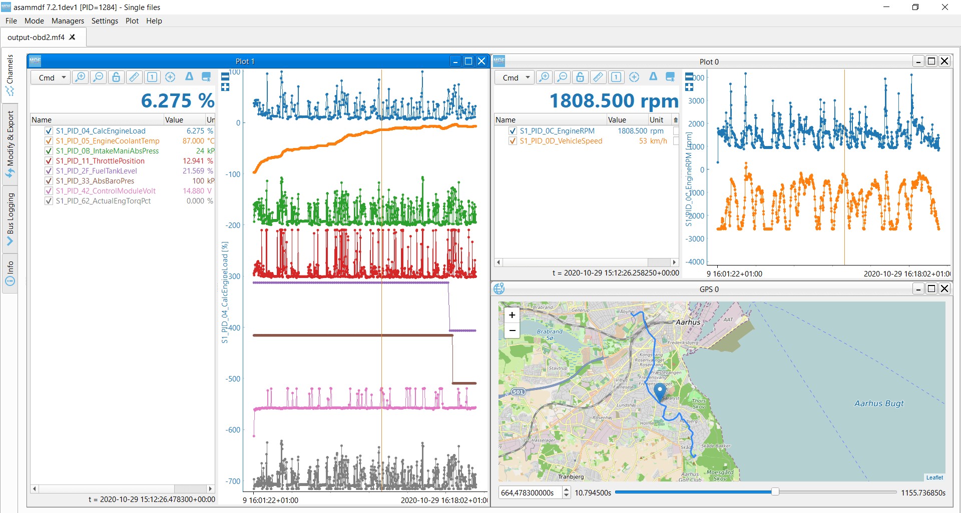 OBD2 data decoded visual plot asammdf CAN bus DBC file
8. What Are Multi-Frame OBD2 Examples Using ISO-TP?
All OBD2 data is communicated using the ISO-TP (transport protocol) as per ISO 15765-2. Most of the examples so far reflect single-frame communication. In this section, we provide some examples of multi-frame communication.
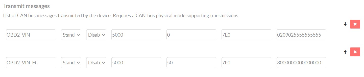
Multi-frame OBD2 communication requires flow control frames (see our UDS intro). In practice, this can be done by transmitting a static flow control frame e.g. 50 ms after the initial request frame, as per the CANedge configuration example shown.
Further, multi-frame OBD2 responses require CAN software/API tools that support ISO-TP, like the CANedge MF4 decoders.
 OBD2-multi-frame-request-message-vehicle-identification-number
8.1. OBD2 Vehicle Identification Number (VIN)
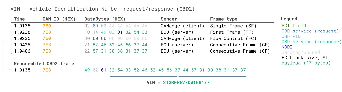
To extract the Vehicle Identification Number from a vehicle using OBD2 requests, you use mode 0x09 and PID 0x02:
- The tester tool sends a Single Frame request with the PCI field (0x02), request service identifier (0x09) and PID (0x02).
- The vehicle responds with a First Frame containing the PCI, length (0x014 = 20 bytes), mode (0x49, i.e. 0x09 + 0x40) and PID (0x02). Following the PID is the byte 0x01 which is the Number Of Data Items (NODI), in this case 1 (see ISO 15031-5 / SAE J1979 for details). The remaining 17 bytes equal the VIN and can be translated from HEX to ASC via methods discussed in our intro to UDS.
 VIN Vehicle Identification Number OBD2 Example multi-frame
8.2. OBD2 Multi-PID Request (6x)
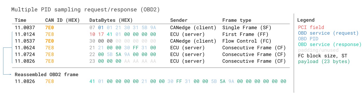
External tools are allowed to request up to 6 mode 0x01 OBD2 PIDs in a single request frame. The ECU shall respond with data for supported PIDs (with unsupported PIDs left out of the response), if necessary across multiple frames as per ISO-TP.
 Requesting multiple PIDs in one request
The multi-frame response is similar to the VIN example, though with the twist that the payload includes the requested PIDs as well as the data for each of them.
8.3. OBD2 Diagnostic Trouble Codes (DTCs)
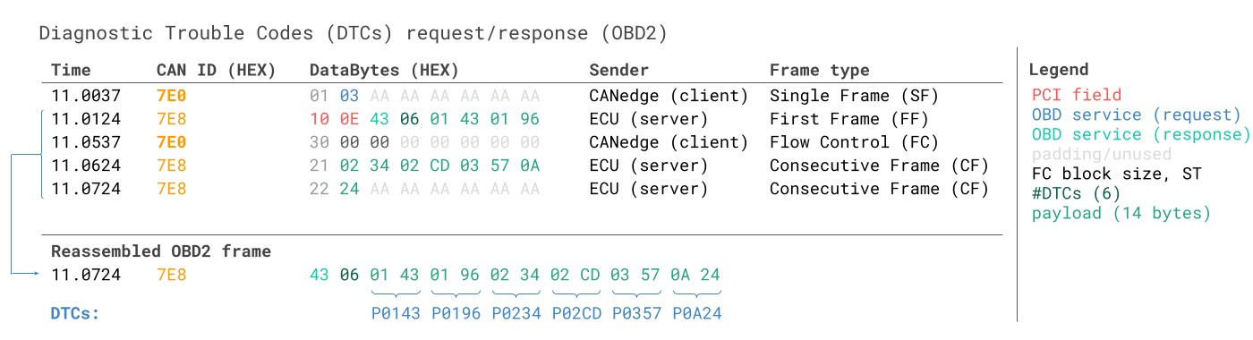
You can use OBD2 to request emissions-related Diagnostic Trouble Codes (DTCs) from using mode 0x03, i.e. ‘Show stored Diagnostic Trouble Codes’. No PID is included in the request. The targeted ECU(s) will then respond with the number of DTCs they have stored (including potentially 0 if they have none), with each DTC taking up 2 data bytes. As a result, multi-frame responses are necessary when more than 2 DTCs are stored.
The 2-byte DTC value is typically split into two parts, as per ISO 15031-5/ISO 15031-6. The first 2 bits define the ‘category’, while the remaining 14 bits define a 4-digit code (displayed in hexadecimal), as per the visual. The decoded DTC values can be looked up in various OBD2 DTC lookup tools like repairpal.com.
Below example shows a request to an ECU with 6 DTCs stored.
 OBD2 Diagnostic Trouble Codes DTC CAN Bus Request Response Example
9. What Are Use Cases For OBD2 Data Logging?
OBD2 data from cars and light trucks can be used in various use cases:
9.1. Logging Data from Cars
OBD2 data from cars can e.g. be used to reduce fuel costs, improve driving, test prototype parts and insurance
9.2. Real-Time Car Diagnostics
OBD2 interfaces can be used to stream human-readable OBD2 data in real-time, e.g. for diagnosing vehicle issues
9.3. Predictive Maintenance
Cars and light trucks can be monitored via IoT OBD2 loggers in the cloud to predict and avoid breakdowns
9.4. Vehicle Blackbox Logger
An OBD2 logger can serve as a ‘blackbox’ for vehicles or equipment, providing data for e.g. disputes or diagnostics
10. FAQ About OBD2 Communication Protocol
10.1. What is an OBD2 Scanner?
An OBD2 scanner is a diagnostic tool used to read data from a vehicle’s onboard computer system. It connects to the OBD2 port, typically located under the dashboard, and retrieves diagnostic trouble codes (DTCs) and real-time data to help identify and troubleshoot vehicle issues.
10.2. How Do I Read OBD2 Codes?
To read OBD2 codes, you need an OBD2 scanner. Plug the scanner into the OBD2 port, turn on the ignition, and follow the scanner’s instructions to retrieve the codes. Once you have the codes, you can look them up in a database or online to understand the issue.
10.3. What Are Common OBD2 Codes and Their Meanings?
Some common OBD2 codes include:
- P0171: System Too Lean (Bank 1) – Indicates that the engine is receiving too much air or not enough fuel.
- P0300: Random/Multiple