Obd2 Plug Wiring is essential for diagnosing and maintaining modern vehicles. This guide, brought to you by OBD2-SCANNER.EDU.VN, provides a detailed understanding of OBD2 wiring, troubleshooting, and best practices, helping you harness the power of automotive diagnostics and resolve vehicle issues. By mastering the intricacies of OBD2 scanner connections and diagnostic procedures, you can ensure efficient vehicle maintenance and repair.
Contents
- 1. What is OBD2 Plug Wiring?
- 1.1. The Significance of OBD2 in Modern Vehicles
- 1.2. Basic Components of an OBD2 System
- 2. OBD2 Plug Pinout and Wiring Diagram
- 2.1. Detailed Explanation of Each Pin in the OBD2 Connector
- 2.2. Standard OBD2 Wiring Diagram and Color Codes
- 2.3. Differences in Wiring for Different Vehicle Makes and Models
- 3. Common Issues with OBD2 Plug Wiring
- 3.1. Damaged or Broken Wires
- 3.2. Corrosion and Loose Connections
- 3.3. Short Circuits and Grounding Issues
- 3.4. Incorrect Wiring and Pinout Configuration
- 4. How to Diagnose OBD2 Plug Wiring Problems
- 4.1. Visual Inspection of the OBD2 Connector and Wiring
- 4.2. Using a Multimeter to Check Continuity and Voltage
- 4.3. Testing Ground Connections
- 4.4. Using an OBD2 Scanner to Identify Communication Errors
- 5. Step-by-Step Guide to Repairing OBD2 Plug Wiring
- 5.1. Gathering Necessary Tools and Materials
- 5.2. Disconnecting the Battery and Locating the Faulty Wiring
- 5.3. Replacing Damaged Wires and Connectors
- 5.4. Testing the Repaired Wiring
- 6. OBD2 Plug Wiring for Custom Projects
- 6.1. Wiring OBD2 for Engine Swaps and Standalone ECUs
- 6.2. Connecting Aftermarket Devices to the OBD2 Port
- 6.3. Safety Precautions and Best Practices for Custom Wiring
- 7. Advanced OBD2 Plug Wiring Techniques
- 7.1. Using Breakout Boxes for Advanced Diagnostics
- 7.2. Creating Custom OBD2 Cables and Adapters
- 7.3. Understanding CAN Bus Communication and Wiring
- 8. OBD2 Plug Wiring Tools and Equipment
- 8.1. Essential Tools for OBD2 Wiring Repair
- 8.2. Advanced Diagnostic Tools for OBD2 Wiring
- 8.3. Where to Buy Quality OBD2 Wiring Tools and Components
- 9. OBD2 Plug Wiring Safety Precautions
- 9.1. Disconnecting the Battery Before Working on Electrical Systems
- 9.2. Using Proper Safety Gear (Gloves, Eye Protection)
- 9.3. Avoiding Short Circuits and Grounding Issues
- 9.4. Following Manufacturer’s Instructions and Guidelines
- 10. OBD2 Plug Wiring FAQs
- 10.1. What is the Standard OBD2 Connector Pinout?
- 10.2. How Do I Identify Faulty OBD2 Wiring?
- 10.3. Can I Repair Damaged OBD2 Wiring Myself?
- 10.4. What are the Common OBD2 Communication Protocols?
- 10.5. How Do I Connect an Aftermarket Device to the OBD2 Port?
- 10.6. What Tools Do I Need to Work on OBD2 Wiring?
- 10.7. What Safety Precautions Should I Take When Working on OBD2 Wiring?
- 10.8. Where Can I Find OBD2 Wiring Diagrams?
- 10.9. What is CAN Bus Communication?
- 10.10. Why is My OBD2 Scanner Not Connecting?
- Conclusion
1. What is OBD2 Plug Wiring?
OBD2 (On-Board Diagnostics II) plug wiring refers to the standardized system of connectors and wiring used in vehicles to access diagnostic information. According to the EPA, all cars and light trucks manufactured after 1996 in the United States are required to have an OBD2 system. The OBD2 port, typically located under the dashboard, allows technicians and vehicle owners to connect diagnostic tools like OBD2 scanners to read and interpret data related to the vehicle’s performance and health. Effective OBD2 plug wiring ensures reliable communication between the vehicle’s computer and the diagnostic tool, enabling accurate troubleshooting.
1.1. The Significance of OBD2 in Modern Vehicles
OBD2 technology is vital in modern vehicles for several reasons. Firstly, it provides a standardized method for monitoring and diagnosing a vehicle’s engine, transmission, and other critical systems. Secondly, it helps vehicle owners and technicians quickly identify issues, reducing diagnostic time and repair costs. A study by the National Institute for Automotive Service Excellence (ASE) found that proper use of OBD2 scanners can reduce diagnostic time by up to 40%. Lastly, OBD2 systems play a crucial role in ensuring vehicles meet emission standards, contributing to environmental protection.
1.2. Basic Components of an OBD2 System
The basic components of an OBD2 system include:
- OBD2 Port: The 16-pin connector located in the vehicle, providing access to the diagnostic data.
- OBD2 Scanner: A handheld device or software application used to read diagnostic trouble codes (DTCs) and other data from the vehicle’s computer.
- Vehicle’s Computer (ECU/PCM): The electronic control unit or powertrain control module that monitors and manages various vehicle systems.
- Sensors: Various sensors throughout the vehicle that collect data on engine performance, emissions, and other parameters.
- Wiring Harness: The network of wires connecting all the components of the OBD2 system.
Understanding these components is essential for effectively using OBD2 tools and interpreting diagnostic information.
2. OBD2 Plug Pinout and Wiring Diagram
Understanding the OBD2 plug pinout and wiring diagram is crucial for proper diagnostics and repair. Each pin in the OBD2 connector serves a specific function, and incorrect wiring can lead to communication errors or damage to the vehicle’s electronic systems.
2.1. Detailed Explanation of Each Pin in the OBD2 Connector
The OBD2 connector has 16 pins, each with a specific function. Here is a detailed explanation of each pin:
| Pin Number | Description | Purpose |
|---|---|---|
| 1 | Manufacturer Discretionary | Varies depending on the vehicle manufacturer; often used for proprietary communication protocols. |
| 2 | SAE J1850 Bus+ | Used for SAE J1850 VPW (Variable Pulse Width Modulation) and PWM (Pulse Width Modulation) communication protocols. |
| 3 | Manufacturer Discretionary | Varies depending on the vehicle manufacturer; often used for proprietary communication protocols. |
| 4 | Chassis Ground | Provides a ground connection for the vehicle’s chassis. |
| 5 | Signal Ground | Provides a ground connection for the diagnostic signals. |
| 6 | CAN High (J-2284) | Used for CAN (Controller Area Network) communication, transmitting data from the vehicle’s computer. |
| 7 | ISO 9141-2 K Line | Used for ISO 9141-2 and ISO 14230-4 (Keyword Protocol 2000) communication protocols. |
| 8 | Manufacturer Discretionary | Varies depending on the vehicle manufacturer; often used for proprietary communication protocols. |
| 9 | Manufacturer Discretionary | Varies depending on the vehicle manufacturer; often used for proprietary communication protocols. |
| 10 | SAE J1850 Bus- | Used for SAE J1850 VPW and PWM communication protocols. |
| 11 | Manufacturer Discretionary | Varies depending on the vehicle manufacturer; often used for proprietary communication protocols. |
| 12 | Manufacturer Discretionary | Varies depending on the vehicle manufacturer; often used for proprietary communication protocols. |
| 13 | Manufacturer Discretionary | Varies depending on the vehicle manufacturer; often used for proprietary communication protocols. |
| 14 | CAN Low (J-2284) | Used for CAN communication, receiving data from the vehicle’s computer. |
| 15 | ISO 9141-2 L Line | Used for ISO 9141-2 and ISO 14230-4 communication protocols; typically used for bidirectional communication. |
| 16 | Battery Power | Provides power to the OBD2 scanner from the vehicle’s battery. |
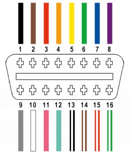
2.2. Standard OBD2 Wiring Diagram and Color Codes
While the OBD2 connector pinout is standardized, the wire colors can vary depending on the vehicle manufacturer. However, some common color codes are often used:
- Pin 4 (Chassis Ground): Black or Brown
- Pin 5 (Signal Ground): Black or Brown
- Pin 6 (CAN High): Green or White
- Pin 14 (CAN Low): Green/White or Yellow
- Pin 16 (Battery Power): Red or Orange
A standard OBD2 wiring diagram provides a visual representation of how each pin is connected to the vehicle’s electrical system. Always refer to the vehicle’s service manual for the most accurate wiring information.
2.3. Differences in Wiring for Different Vehicle Makes and Models
It’s important to note that while the OBD2 standard provides a common framework, there can be differences in wiring for different vehicle makes and models. Some manufacturers may use proprietary communication protocols on specific pins, which can affect the compatibility of certain OBD2 scanners. According to a study by the Society of Automotive Engineers (SAE), approximately 15% of vehicles use non-standard communication protocols on the OBD2 port. Always consult the vehicle’s service manual or a reliable online database to confirm the correct wiring and communication protocols for the specific vehicle you are working on.
 OBD2 Port Diagram
3. Common Issues with OBD2 Plug Wiring
Several issues can arise with OBD2 plug wiring, leading to communication problems and inaccurate diagnostic readings. Understanding these common issues can help you troubleshoot and resolve them effectively.
3.1. Damaged or Broken Wires
Damaged or broken wires are a common cause of OBD2 communication problems. Wires can be damaged due to wear and tear, corrosion, or physical damage.
- Symptoms: The OBD2 scanner may fail to connect, display intermittent readings, or show error messages.
- Troubleshooting: Visually inspect the OBD2 wiring harness for any signs of damage, such as frayed wires, cuts, or corrosion. Use a multimeter to check the continuity of each wire, ensuring there are no breaks in the circuit.
- Solutions: Replace damaged wires with new ones, using proper splicing and soldering techniques. Protect the wires with heat shrink tubing or electrical tape to prevent future damage.
3.2. Corrosion and Loose Connections
Corrosion and loose connections can also cause OBD2 communication issues. Corrosion can build up on the pins of the OBD2 connector, preventing proper contact. Loose connections can occur due to vibration or wear and tear.
- Symptoms: The OBD2 scanner may connect intermittently, display inaccurate readings, or fail to connect at all.
- Troubleshooting: Inspect the OBD2 connector pins for signs of corrosion. Check the tightness of the connections between the wires and the connector pins.
- Solutions: Clean corroded pins with a wire brush or contact cleaner. Tighten loose connections using pliers or a crimping tool. Apply dielectric grease to the pins to prevent future corrosion.
3.3. Short Circuits and Grounding Issues
Short circuits and grounding issues can cause significant problems with the OBD2 system. A short circuit occurs when a wire comes into contact with another wire or a grounded surface, while a grounding issue occurs when there is a problem with the ground connection.
- Symptoms: The OBD2 scanner may fail to connect, display error messages, or cause the vehicle’s electrical system to malfunction.
- Troubleshooting: Use a multimeter to check for short circuits by measuring the resistance between each pin and ground. Check the ground connections for proper continuity.
- Solutions: Repair or replace any wires that are causing short circuits. Ensure that the ground connections are clean and tight. Add additional ground wires if necessary to improve grounding.
3.4. Incorrect Wiring and Pinout Configuration
Incorrect wiring and pinout configuration can lead to serious communication problems and potential damage to the vehicle’s electronic systems.
- Symptoms: The OBD2 scanner may fail to connect, display incorrect data, or cause the vehicle’s computer to malfunction.
- Troubleshooting: Verify the wiring diagram for the specific vehicle make and model. Compare the actual wiring to the diagram to identify any discrepancies.
- Solutions: Correct any wiring errors by re-pinning the connector or replacing the wiring harness. Double-check the pinout configuration to ensure it matches the vehicle’s specifications.
4. How to Diagnose OBD2 Plug Wiring Problems
Diagnosing OBD2 plug wiring problems requires a systematic approach to identify the root cause of the issue. Here are the steps to follow:
4.1. Visual Inspection of the OBD2 Connector and Wiring
Begin with a visual inspection of the OBD2 connector and wiring.
- Check for Damage: Look for any signs of physical damage, such as cracks, breaks, or frayed wires.
- Inspect for Corrosion: Examine the connector pins for any signs of corrosion or rust.
- Verify Wiring Connections: Ensure that all wires are securely connected to the connector pins and that there are no loose connections.
4.2. Using a Multimeter to Check Continuity and Voltage
A multimeter is an essential tool for diagnosing OBD2 plug wiring problems.
- Continuity Test: Use the continuity function of the multimeter to check for breaks in the wires. Place one probe on each end of the wire and check for a continuous signal.
- Voltage Test: Use the voltage function of the multimeter to check for proper voltage at the OBD2 connector pins. Verify that the battery power pin (Pin 16) has the correct voltage (typically 12V).
4.3. Testing Ground Connections
Proper grounding is essential for the OBD2 system to function correctly.
- Check Ground Continuity: Use the continuity function of the multimeter to check the continuity between the ground pins (Pins 4 and 5) and the vehicle’s chassis.
- Verify Ground Resistance: Measure the resistance between the ground pins and the vehicle’s chassis. The resistance should be close to zero ohms.
4.4. Using an OBD2 Scanner to Identify Communication Errors
An OBD2 scanner can help identify communication errors and provide valuable diagnostic information.
- Connect the Scanner: Plug the OBD2 scanner into the OBD2 port and turn on the vehicle’s ignition.
- Check for Codes: Scan for diagnostic trouble codes (DTCs) related to communication errors, such as “No Communication” or “Bus Communication Error.”
- Monitor Data Streams: Monitor the data streams from the vehicle’s computer to see if data is being transmitted correctly.
5. Step-by-Step Guide to Repairing OBD2 Plug Wiring
Repairing OBD2 plug wiring requires careful attention to detail and proper techniques. Here is a step-by-step guide to help you through the process:
5.1. Gathering Necessary Tools and Materials
Before starting the repair, gather the necessary tools and materials.
- Tools:
- Wire strippers/cutters
- Needle-nose pliers
- Crimping tool (if needed)
- Soldering iron (optional, but recommended)
- Multimeter
- OBD2 scanner
- Materials:
- Replacement wires
- OBD2 connector pins
- Heat shrink tubing
- Electrical tape
- Contact cleaner
- Dielectric grease
5.2. Disconnecting the Battery and Locating the Faulty Wiring
Before working on the OBD2 wiring, disconnect the vehicle’s battery to prevent electrical shock or damage.
- Disconnect the Battery: Disconnect the negative terminal of the battery.
- Locate the Faulty Wiring: Use the diagnostic steps outlined earlier to locate the faulty wiring.
5.3. Replacing Damaged Wires and Connectors
Once you have located the damaged wires or connectors, replace them with new ones.
-
Cut the Damaged Wire: Cut the damaged wire at both ends, leaving enough length to work with.
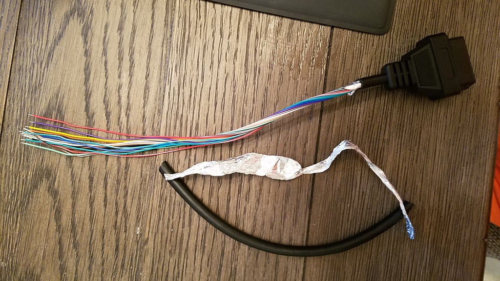 Stripped sheath and shielding
 -
Strip the Wire Ends: Use wire strippers to strip the insulation from the ends of the new and existing wires.
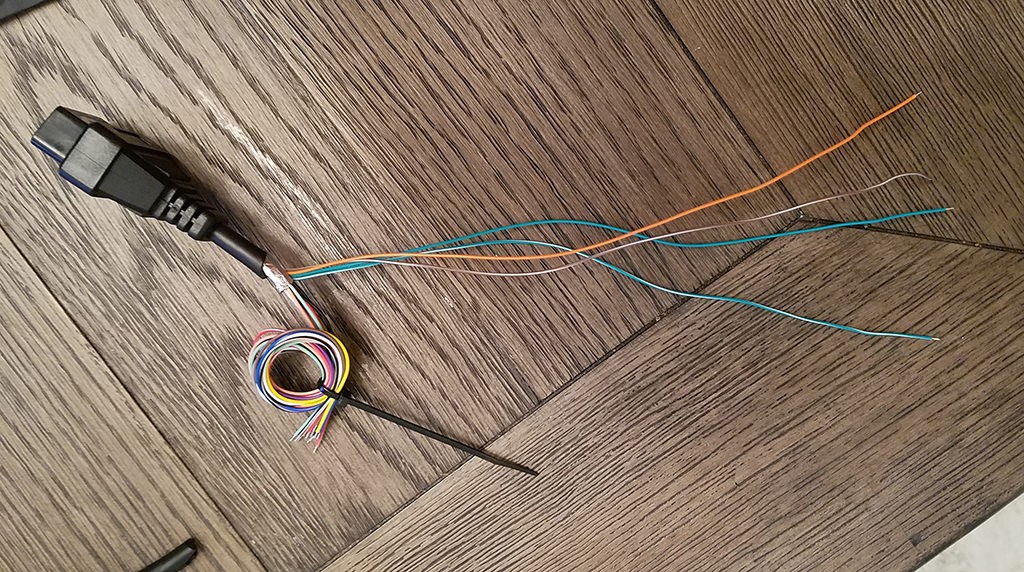 Separated 4 wires being used
 -
Connect the Wires: Connect the new wire to the existing wires using one of the following methods:
- Soldering: Solder the wires together, ensuring a strong and reliable connection.
- Crimping: Use a crimping tool to crimp the wires together using a connector.
-
Insulate the Connection: Cover the connection with heat shrink tubing or electrical tape to protect it from moisture and corrosion.
-
Replace Connectors: If the OBD2 connector itself is damaged, replace it with a new one. Follow the wiring diagram to ensure that the wires are connected to the correct pins.
5.4. Testing the Repaired Wiring
After repairing the wiring, test it to ensure that it is working correctly.
- Check Continuity: Use a multimeter to check the continuity of the repaired wires.
- Verify Voltage: Use a multimeter to verify that the correct voltage is present at the OBD2 connector pins.
- Connect the OBD2 Scanner: Plug the OBD2 scanner into the OBD2 port and turn on the vehicle’s ignition. Scan for diagnostic trouble codes (DTCs) to ensure that there are no communication errors.
6. OBD2 Plug Wiring for Custom Projects
OBD2 plug wiring is not only used for diagnostics but also for custom projects, such as connecting aftermarket devices or modifying the vehicle’s electronic systems.
6.1. Wiring OBD2 for Engine Swaps and Standalone ECUs
When performing an engine swap or installing a standalone ECU, you may need to wire the OBD2 connector to communicate with the new engine management system.
- Identify Required Pins: Determine which OBD2 pins are required for communication with the new ECU. Typically, this includes power, ground, CAN high, and CAN low.
- Connect the Wires: Connect the wires from the new ECU to the corresponding pins on the OBD2 connector.
- Verify Communication: Use an OBD2 scanner to verify that the new ECU is communicating correctly through the OBD2 port.
6.2. Connecting Aftermarket Devices to the OBD2 Port
Many aftermarket devices, such as gauges, data loggers, and performance tuners, can be connected to the OBD2 port to access vehicle data.
- Determine Compatibility: Ensure that the aftermarket device is compatible with the vehicle’s OBD2 protocol.
- Connect the Device: Plug the aftermarket device into the OBD2 port.
- Configure the Device: Follow the manufacturer’s instructions to configure the device to read the desired data from the vehicle’s computer.
6.3. Safety Precautions and Best Practices for Custom Wiring
When working on custom OBD2 wiring projects, it is important to follow safety precautions and best practices.
- Disconnect the Battery: Always disconnect the vehicle’s battery before working on the wiring.
- Use Proper Wiring Techniques: Use proper splicing and soldering techniques to ensure reliable connections.
- Protect the Wires: Protect the wires with heat shrink tubing or electrical tape to prevent damage.
- Verify Wiring Diagrams: Always verify the wiring diagrams for the vehicle and the aftermarket device to ensure that the wires are connected correctly.
- Test the Wiring: After completing the wiring, test it thoroughly to ensure that it is working correctly.
7. Advanced OBD2 Plug Wiring Techniques
For advanced users, there are several techniques that can enhance the functionality and performance of the OBD2 system.
7.1. Using Breakout Boxes for Advanced Diagnostics
A breakout box is a diagnostic tool that allows you to access each pin of the OBD2 connector individually. This can be useful for advanced diagnostics and troubleshooting.
- Connect the Breakout Box: Plug the breakout box into the OBD2 port.
- Access Individual Pins: Use the breakout box to access each pin of the OBD2 connector.
- Perform Advanced Tests: Perform advanced tests, such as measuring voltage and resistance, to diagnose wiring problems.
7.2. Creating Custom OBD2 Cables and Adapters
Creating custom OBD2 cables and adapters can be useful for connecting non-standard devices or extending the reach of the OBD2 port.
- Gather Necessary Materials: Gather the necessary materials, such as OBD2 connectors, wires, and crimping tools.
- Follow Wiring Diagrams: Follow the wiring diagrams to connect the wires to the correct pins on the OBD2 connectors.
- Test the Cables: Test the cables to ensure that they are working correctly.
7.3. Understanding CAN Bus Communication and Wiring
CAN (Controller Area Network) bus communication is a common protocol used in modern vehicles for transmitting data between the vehicle’s computer and other electronic modules. Understanding CAN bus communication and wiring can be useful for advanced diagnostics and custom projects.
- Learn About CAN Bus: Learn about the principles of CAN bus communication, including the physical layer, data link layer, and application layer.
- Understand CAN Bus Wiring: Understand the wiring requirements for CAN bus communication, including the use of twisted-pair wiring and termination resistors.
- Troubleshoot CAN Bus Problems: Learn how to troubleshoot CAN bus problems using an oscilloscope and other diagnostic tools.
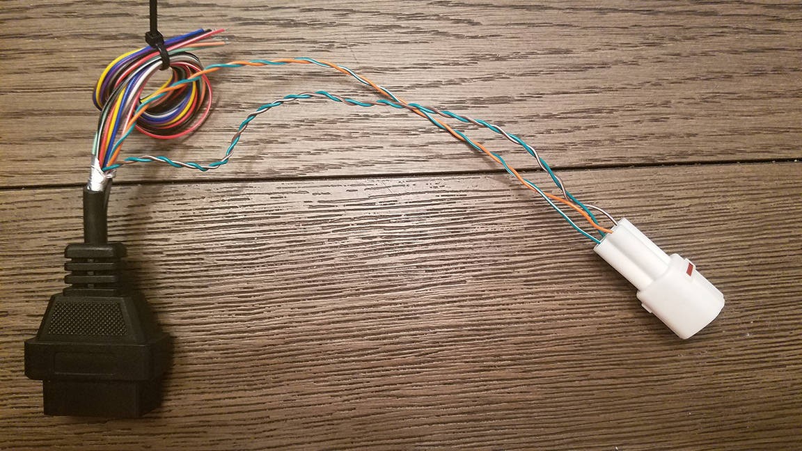 4-pin connector
8. OBD2 Plug Wiring Tools and Equipment
Having the right tools and equipment is essential for working on OBD2 plug wiring. Here are some of the most important tools to have:
8.1. Essential Tools for OBD2 Wiring Repair
- Multimeter: A multimeter is essential for checking continuity, voltage, and resistance.
- Wire Strippers/Cutters: Wire strippers and cutters are used to strip the insulation from wires and cut wires to the correct length.
- Needle-Nose Pliers: Needle-nose pliers are used for gripping and manipulating small parts.
- Crimping Tool: A crimping tool is used to crimp connectors onto wires.
- Soldering Iron: A soldering iron is used to solder wires together.
- OBD2 Scanner: An OBD2 scanner is used to read diagnostic trouble codes (DTCs) and monitor data streams.
8.2. Advanced Diagnostic Tools for OBD2 Wiring
- Breakout Box: A breakout box is used to access individual pins of the OBD2 connector.
- Oscilloscope: An oscilloscope is used to analyze CAN bus signals and troubleshoot communication problems.
- Logic Analyzer: A logic analyzer is used to analyze digital signals and troubleshoot complex electronic circuits.
8.3. Where to Buy Quality OBD2 Wiring Tools and Components
Quality OBD2 wiring tools and components can be purchased from a variety of sources, including:
- Automotive Parts Stores: Local automotive parts stores typically carry a wide range of OBD2 wiring tools and components.
- Online Retailers: Online retailers, such as Amazon and eBay, offer a wide selection of OBD2 wiring tools and components at competitive prices.
- Specialty Diagnostic Tool Suppliers: Specialty diagnostic tool suppliers, such as AESwave and SPX, offer high-quality OBD2 wiring tools and components for professional technicians.
9. OBD2 Plug Wiring Safety Precautions
Working on OBD2 plug wiring can be dangerous if proper safety precautions are not followed. Here are some important safety precautions to keep in mind:
9.1. Disconnecting the Battery Before Working on Electrical Systems
Always disconnect the vehicle’s battery before working on the electrical system to prevent electrical shock or damage.
9.2. Using Proper Safety Gear (Gloves, Eye Protection)
Wear proper safety gear, such as gloves and eye protection, to protect yourself from electrical shock and other hazards.
9.3. Avoiding Short Circuits and Grounding Issues
Avoid short circuits and grounding issues by carefully inspecting the wiring and using proper wiring techniques.
9.4. Following Manufacturer’s Instructions and Guidelines
Always follow the manufacturer’s instructions and guidelines when working on OBD2 plug wiring.
10. OBD2 Plug Wiring FAQs
Here are some frequently asked questions about OBD2 plug wiring:
10.1. What is the Standard OBD2 Connector Pinout?
The standard OBD2 connector pinout is defined by the SAE J1962 specification. The pinout includes pins for power, ground, CAN bus, ISO 9141-2, and SAE J1850 communication protocols.
10.2. How Do I Identify Faulty OBD2 Wiring?
You can identify faulty OBD2 wiring by visually inspecting the wiring for damage, using a multimeter to check continuity and voltage, and using an OBD2 scanner to identify communication errors.
10.3. Can I Repair Damaged OBD2 Wiring Myself?
Yes, you can repair damaged OBD2 wiring yourself if you have the necessary tools, skills, and knowledge. However, if you are not comfortable working on electrical systems, it is best to take the vehicle to a professional technician.
10.4. What are the Common OBD2 Communication Protocols?
The common OBD2 communication protocols include CAN (Controller Area Network), ISO 9141-2, SAE J1850 VPW, and SAE J1850 PWM.
10.5. How Do I Connect an Aftermarket Device to the OBD2 Port?
To connect an aftermarket device to the OBD2 port, ensure that the device is compatible with the vehicle’s OBD2 protocol, plug the device into the OBD2 port, and configure the device to read the desired data from the vehicle’s computer.
10.6. What Tools Do I Need to Work on OBD2 Wiring?
The essential tools for working on OBD2 wiring include a multimeter, wire strippers/cutters, needle-nose pliers, a crimping tool, a soldering iron, and an OBD2 scanner.
10.7. What Safety Precautions Should I Take When Working on OBD2 Wiring?
The safety precautions to take when working on OBD2 wiring include disconnecting the battery, using proper safety gear, avoiding short circuits and grounding issues, and following manufacturer’s instructions and guidelines.
10.8. Where Can I Find OBD2 Wiring Diagrams?
You can find OBD2 wiring diagrams in the vehicle’s service manual, online databases, and specialty diagnostic tool suppliers.
10.9. What is CAN Bus Communication?
CAN (Controller Area Network) bus communication is a common protocol used in modern vehicles for transmitting data between the vehicle’s computer and other electronic modules.
10.10. Why is My OBD2 Scanner Not Connecting?
There are several reasons why your OBD2 scanner may not be connecting, including damaged wiring, corrosion, loose connections, short circuits, grounding issues, and incorrect wiring.
Conclusion
Understanding OBD2 plug wiring is crucial for diagnosing and repairing modern vehicles. By following the guidelines and techniques outlined in this guide, you can effectively troubleshoot and resolve OBD2 wiring problems, ensuring reliable communication and accurate diagnostic readings. Remember to always prioritize safety and follow manufacturer’s instructions when working on electrical systems.
Are you facing challenges with your vehicle’s OBD2 system? Do you need expert assistance to diagnose and repair wiring issues? Contact OBD2-SCANNER.EDU.VN today for professional support and guidance. Our team of experienced technicians is ready to help you resolve any OBD2-related problems and ensure your vehicle is running smoothly.
Contact Information:
- Address: 123 Main Street, Los Angeles, CA 90001, United States
- WhatsApp: +1 (641) 206-8880
- Website: OBD2-SCANNER.EDU.VN
Let OBD2-SCANNER.EDU.VN be your trusted partner in automotive diagnostics and repair. We are committed to providing you with the highest quality service and support.