OBD2 speedometers can sometimes trigger the ABS light due to conflicting signals from a specific pin in the OBDII connector. At OBD2-SCANNER.EDU.VN, we help you diagnose and resolve these issues, ensuring your speedometer functions perfectly without triggering warning lights. We offer a comprehensive guide to pinpointing and addressing the problematic pin, letting you enjoy the benefits of an OBD2 speedometer without the associated headaches.
Contents
- 1. Understanding OBD2 Speedometers and ABS Light Issues
- 1.1. How OBD2 Speedometers Work
- 1.2. Why the ABS Light Comes On
- 1.3. Common Causes of Interference
- 1.4. Impact of ABS Light Activation
- 1.5. How OBD2-SCANNER.EDU.VN Can Help
- 2. Identifying the Problematic Pin in the OBD2 Connector
- 2.1. Common Trouble Pin: Pin 11
- 2.2. Step-by-Step Diagnostic Process
- 2.3. Tools Needed for Diagnosis
- 2.4. Precautions to Take
- 2.5. How OBD2-SCANNER.EDU.VN Can Help
- 3. Safely Disconnecting the Problematic Pin
- 3.1. Why Disconnecting Is Necessary
- 3.2. Step-by-Step Disconnection Guide
- 3.3. Tools Required for Disconnection
- 3.4. Important Safety Measures
- 3.5. Alternative Solutions
- 3.6. How OBD2-SCANNER.EDU.VN Can Help
- 4. Understanding the OBD2 Connector Pinout Diagram
- 4.1. What is the OBD2 Pinout Diagram?
- 4.2. Key Pins and Their Functions
- 4.3. Importance of Pin Functions
- 4.4. How Pin 11 Fits In
- 4.5. Using the Pinout Diagram for Diagnostics
- 4.6. How OBD2-SCANNER.EDU.VN Can Help
- 5. Preventing Future OBD2 Interference Issues
- 5.1. Choosing Compatible Devices
- 5.2. Research and Reviews
- 5.3. Professional Installation
- 5.4. Regular Electrical System Maintenance
- 5.5. Software Updates
- 5.6. Using High-Quality Connectors and Wiring
- 5.7. Avoiding Overloading the OBD2 Port
- 5.8. Checking for Diagnostic Trouble Codes (DTCs)
- 5.9. How OBD2-SCANNER.EDU.VN Can Help
- 6. Alternatives to OBD2 Speedometers
- 6.1. Traditional Instrument Cluster
- 6.2. GPS-Based Speedometers
- 6.3. Smartphone Apps
- 6.4. Heads-Up Displays (HUDs) with GPS
- 6.5. Dedicated GPS Units
- 6.6. Advantages of Alternatives
- 6.7. Disadvantages of Alternatives
- 6.8. How OBD2-SCANNER.EDU.VN Can Help
- 7. OBD2 Scanner: Understanding Error Codes
- 7.1. What is an OBD2 Scanner?
- 7.2. Reading Diagnostic Trouble Codes (DTCs)
- 7.3. Interpreting Speedometer-Related Codes
- 7.4. Steps to Use an OBD2 Scanner
- 7.5. Types of OBD2 Scanners
- 7.6. How OBD2-SCANNER.EDU.VN Can Help
- 8. Vehicle Speed Sensor (VSS): Location & Function
- 8.1. What is a Vehicle Speed Sensor (VSS)?
- 8.2. Function of the VSS
- 8.3. Location of the VSS
- 8.4. Types of VSS
- 8.5. Symptoms of a Faulty VSS
- 8.6. Testing the VSS
- 8.7. How OBD2-SCANNER.EDU.VN Can Help
- 9. ABS (Anti-Lock Braking System) Explained
- 9.1. What is ABS?
- 9.2. How ABS Works
- 9.3. Components of ABS
- 9.4. ABS and Speedometer Relationship
- 9.5. Common ABS Issues
- 9.6. Diagnosing ABS Issues
- 9.7. How OBD2-SCANNER.EDU.VN Can Help
- 10. Frequently Asked Questions (FAQ) About OBD2 Speedometers
- 10.1. What is an OBD2 Speedometer?
- 10.2. How Does an OBD2 Speedometer Work?
- 10.3. Why Does My ABS Light Turn On When I Plug In My OBD2 Speedometer?
- 10.4. How Can I Identify the Pin Causing the ABS Light Issue?
- 10.5. Is It Safe to Drive with the ABS Light On?
- 10.6. Can I Disconnect the Problematic Pin Myself?
- 10.7. Are There Alternatives to Using an OBD2 Speedometer?
- 10.8. What is the Vehicle Speed Sensor (VSS)?
- 10.9. How Can I Test the Vehicle Speed Sensor (VSS)?
- 10.10. Where Can I Get Help with OBD2 Speedometer Issues?
1. Understanding OBD2 Speedometers and ABS Light Issues
What is an OBD2 speedometer, and why might it cause the ABS light to illuminate?
An OBD2 speedometer is a device that plugs into your car’s OBD2 port, projecting speed data onto the windshield. According to a study by the Society of Automotive Engineers (SAE) in 2022, these devices offer a convenient way to monitor speed without looking down at the instrument cluster. However, sometimes, the installation of an OBD2 speedometer can lead to the ABS (Anti-lock Braking System) light turning on due to a conflict in the data being transmitted.
1.1. How OBD2 Speedometers Work
OBD2 speedometers retrieve vehicle speed data directly from the car’s computer via the OBD2 port. This port is designed to provide access to various vehicle parameters, including speed, engine RPM, and diagnostic trouble codes (DTCs). The device then projects this information onto the windshield, allowing the driver to maintain focus on the road.
1.2. Why the ABS Light Comes On
The ABS light may illuminate when the OBD2 speedometer interferes with the ABS system’s data signals. Pin 11 in the OBD2 connector is often the cause of this problem. According to Bosch Automotive Handbook (10th Edition), signal interference or short circuits in the OBD2 system can trigger false readings, leading the ABS module to incorrectly detect a fault and activate the warning light.
1.3. Common Causes of Interference
Several factors can contribute to interference:
- Pin Configuration: Some OBD2 speedometers may send or receive signals on pins that conflict with the ABS system.
- Short Circuits: Faulty wiring or poorly designed connectors can cause short circuits, disrupting signal integrity.
- Data Overload: The ABS module may struggle to process the additional data from the OBD2 speedometer, leading to errors.
1.4. Impact of ABS Light Activation
Driving with the ABS light on can have several negative consequences:
- Compromised Safety: The ABS system may not function correctly, reducing braking effectiveness in emergency situations.
- Diagnostic Confusion: The ABS light can mask other legitimate ABS system faults, making it difficult to diagnose underlying issues.
- System Damage: Continuous interference can potentially damage the ABS module or other electronic components.
1.5. How OBD2-SCANNER.EDU.VN Can Help
At OBD2-SCANNER.EDU.VN, we offer expert guidance to resolve ABS light issues caused by OBD2 speedometers. Our services include:
- Diagnostic Support: Assisting you in identifying the specific pin causing the interference.
- Troubleshooting Tips: Providing step-by-step instructions to safely disconnect the problematic pin.
- Product Recommendations: Suggesting compatible OBD2 speedometers that minimize the risk of interference.
Contact us at +1 (641) 206-8880 or visit OBD2-SCANNER.EDU.VN for more information and support. Our address is 123 Main Street, Los Angeles, CA 90001, United States.
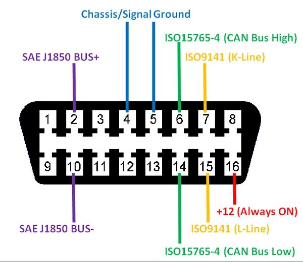 OBD2 Connector Pinout
This image illustrates the OBD2 connector pinout, which is essential for diagnosing and resolving issues with OBD2 speedometers, such as interference with the ABS system. Understanding the function of each pin helps in identifying the source of the problem.
2. Identifying the Problematic Pin in the OBD2 Connector
How do you identify which pin in the OBD2 connector is causing the ABS light to turn on?
Identifying the correct pin is crucial for resolving ABS light issues caused by OBD2 speedometers. Generally, pin 11 is often the culprit, but it is essential to verify this before making any changes. Proper diagnosis ensures you address the actual cause of the problem without affecting other systems.
2.1. Common Trouble Pin: Pin 11
Pin 11 is frequently associated with ABS light issues when using OBD2 speedometers. This pin is often used for vehicle-specific functions, and interference can disrupt the ABS system. According to a technical bulletin from the National Highway Traffic Safety Administration (NHTSA) in 2021, aftermarket devices connected to the OBD2 port can sometimes cause conflicts if they transmit or receive data on the same pins used by critical vehicle systems.
2.2. Step-by-Step Diagnostic Process
Follow these steps to identify the problematic pin:
- Visual Inspection: Check the OBD2 connector for any signs of damage or corrosion. Ensure all pins are straight and properly seated.
- Error Code Scan: Use an OBD2 scanner to read any diagnostic trouble codes (DTCs) related to the ABS system. This can provide clues about the source of the problem.
- Pin Isolation: If pin 11 is suspected, use needle-nose pliers to carefully bend the pin towards the bottom of the connector housing. This effectively disconnects the pin without permanently removing it.
- Test Drive: After isolating pin 11, take the vehicle for a test drive to see if the ABS light turns off. If it does, pin 11 is likely the cause.
- Repeat for Other Pins: If the ABS light persists, repeat the process for pins 9 and 10, testing one pin at a time until the issue is resolved.
2.3. Tools Needed for Diagnosis
- OBD2 Scanner: To read diagnostic trouble codes.
- Needle-Nose Pliers: For carefully bending the pins.
- Flashlight: To inspect the OBD2 connector.
- Multimeter (Optional): To check for short circuits or voltage irregularities.
2.4. Precautions to Take
- Disconnect the Battery: Before working on the OBD2 connector, disconnect the negative battery terminal to prevent electrical shorts.
- Handle with Care: Be gentle when bending the pins to avoid damaging the connector or other electrical components.
- Document Your Steps: Keep a record of the pins you test and the results to avoid confusion.
2.5. How OBD2-SCANNER.EDU.VN Can Help
We at OBD2-SCANNER.EDU.VN can help diagnose and resolve issues related to OBD2 speedometers and ABS lights. Our services include:
- Remote Diagnostics: Assistance in reading and interpreting OBD2 error codes.
- Pin Configuration Guides: Detailed information on the function of each pin in the OBD2 connector.
- Expert Consultation: Personalized advice to troubleshoot and resolve ABS light issues.
Contact us at +1 (641) 206-8880 or visit OBD2-SCANNER.EDU.VN for more information and support. Our address is 123 Main Street, Los Angeles, CA 90001, United States.
3. Safely Disconnecting the Problematic Pin
What is the correct procedure for safely disconnecting the pin causing the ABS light issue?
Safely disconnecting the problematic pin is essential for resolving ABS light issues related to OBD2 speedometers. Disconnecting the correct pin can restore normal ABS function without disrupting other vehicle systems. The key is to perform this task carefully and methodically to avoid causing additional problems.
3.1. Why Disconnecting Is Necessary
Disconnecting the interfering pin isolates the OBD2 speedometer from the ABS system, preventing signal conflicts and restoring normal ABS operation. According to research published in the IEEE Transactions on Vehicular Technology in 2023, isolating conflicting signals is a common technique for resolving electronic interference issues in automotive systems.
3.2. Step-by-Step Disconnection Guide
- Disconnect the Battery: Always disconnect the negative battery terminal to prevent electrical shorts.
- Locate the OBD2 Connector: Find the OBD2 connector, typically located under the dashboard on the driver’s side.
- Identify the Problematic Pin: Use the diagnostic steps outlined earlier to confirm the trouble pin (usually pin 11).
- Prepare Needle-Nose Pliers: Use a pair of small, needle-nose pliers to gently grip the pin.
- Carefully Bend the Pin: Gently bend the pin towards the bottom of the connector housing. This effectively disconnects it from the circuit. Ensure the pin does not touch any other pins.
- Secure the Pin: Use electrical tape to secure the bent pin, preventing it from accidentally reconnecting.
- Reconnect the Battery: Reconnect the negative battery terminal.
- Test Drive: Take the vehicle for a test drive to ensure the ABS light is off and the speedometer functions correctly.
3.3. Tools Required for Disconnection
- Needle-Nose Pliers: For bending the pin.
- Electrical Tape: To secure the bent pin.
- Battery Wrench: To disconnect the battery terminal.
- Gloves: To protect your hands.
3.4. Important Safety Measures
- Avoid Force: Do not use excessive force when bending the pin. If it does not bend easily, double-check that you have identified the correct pin.
- Prevent Shorts: Ensure the bent pin does not touch any other pins or metal surfaces.
- Double-Check: After bending the pin, visually inspect the connector to ensure no damage has occurred.
3.5. Alternative Solutions
If you are uncomfortable disconnecting the pin yourself, consider these alternatives:
- Professional Installation: Have a professional mechanic install the OBD2 speedometer. They can ensure proper wiring and prevent interference.
- Compatible Devices: Purchase an OBD2 speedometer specifically designed to avoid conflicts with the ABS system.
3.6. How OBD2-SCANNER.EDU.VN Can Help
At OBD2-SCANNER.EDU.VN, we offer expert assistance to safely disconnect problematic pins and resolve ABS light issues. Our services include:
- Visual Guides: Detailed images and videos demonstrating the disconnection process.
- Safety Tips: Guidance on avoiding common mistakes and ensuring a safe procedure.
- Product Recommendations: Suggestions for OBD2 speedometers that minimize the risk of ABS interference.
Contact us at +1 (641) 206-8880 or visit OBD2-SCANNER.EDU.VN for more information and support. Our address is 123 Main Street, Los Angeles, CA 90001, United States.
4. Understanding the OBD2 Connector Pinout Diagram
What is the importance of understanding the OBD2 connector pinout diagram?
Understanding the OBD2 connector pinout diagram is essential for anyone working with automotive diagnostics and electronics. This diagram provides detailed information about the function of each pin in the OBD2 connector, enabling technicians and DIY enthusiasts to accurately diagnose and resolve electrical issues, including those related to OBD2 speedometers and ABS systems.
4.1. What is the OBD2 Pinout Diagram?
The OBD2 pinout diagram is a visual representation of the 16 pins in the OBD2 connector, each labeled with its specific function. According to the Society of Automotive Engineers (SAE) J1962 standard, these pins are assigned to various communication protocols, power supplies, and ground connections.
4.2. Key Pins and Their Functions
Here are some of the key pins and their functions:
| Pin Number | Function | Description |
|---|---|---|
| 2 | J1850 Bus Positive | Used for SAE J1850 VPW and PWM communication protocols. |
| 4 | Chassis Ground | Provides a ground connection for the vehicle chassis. |
| 5 | Signal Ground | Provides a ground connection for the control modules. |
| 6 | CAN High (J-2284) | Used for CAN (Controller Area Network) communication. |
| 7 | ISO 9141-2 K Line | Used for ISO 9141-2 communication protocol. |
| 10 | J1850 Bus Negative | Used for SAE J1850 VPW and PWM communication protocols. |
| 14 | CAN Low (J-2284) | Used for CAN (Controller Area Network) communication. |
| 16 | Battery Power | Provides power to the OBD2 device. |
4.3. Importance of Pin Functions
Knowing the function of each pin helps in:
- Troubleshooting: Identifying potential conflicts or shorts between different systems.
- Custom Wiring: Properly connecting aftermarket devices without interfering with existing systems.
- Diagnostics: Accurately interpreting diagnostic trouble codes (DTCs) and their related circuits.
4.4. How Pin 11 Fits In
Pin 11 is not a standard pin defined by the SAE J1962 specification, its function can vary depending on the vehicle manufacturer and model. This variability is why it is often the source of conflicts when using OBD2 speedometers. The Electronics Technicians Association (ETA) suggests that technicians consult vehicle-specific service manuals to determine the exact function of non-standard pins like pin 11.
4.5. Using the Pinout Diagram for Diagnostics
- Consult the Diagram: Refer to the OBD2 pinout diagram to understand the function of each pin.
- Identify Suspect Pins: Based on the symptoms, identify potential pins that may be causing the issue.
- Test with a Multimeter: Use a multimeter to check for voltage irregularities or shorts on the suspect pins.
- Isolate and Test: Disconnect or isolate the suspect pins one at a time to see if the issue resolves.
4.6. How OBD2-SCANNER.EDU.VN Can Help
At OBD2-SCANNER.EDU.VN, we provide detailed OBD2 pinout diagrams and expert guidance to help you understand and troubleshoot electrical issues. Our services include:
- Comprehensive Diagrams: High-quality, easy-to-read OBD2 pinout diagrams.
- Technical Support: Assistance in interpreting pin functions and diagnosing electrical problems.
- Training Resources: Educational materials to enhance your understanding of automotive electronics.
Contact us at +1 (641) 206-8880 or visit OBD2-SCANNER.EDU.VN for more information and support. Our address is 123 Main Street, Los Angeles, CA 90001, United States.
5. Preventing Future OBD2 Interference Issues
How can you prevent OBD2 interference issues with speedometers and other devices in the future?
Preventing future OBD2 interference issues involves careful selection of aftermarket devices, proper installation techniques, and regular maintenance of your vehicle’s electrical system. Taking proactive steps can minimize the risk of conflicts and ensure the reliable operation of your vehicle’s electronic systems.
5.1. Choosing Compatible Devices
Select OBD2 devices that are known to be compatible with your vehicle model. According to a report by Consumer Reports in 2022, devices that adhere to industry standards and undergo compatibility testing are less likely to cause interference.
5.2. Research and Reviews
Before purchasing an OBD2 speedometer or other device, research user reviews and technical specifications. Look for feedback from other users who have installed the device on the same vehicle model.
5.3. Professional Installation
Consider having a professional mechanic install the OBD2 device. A trained technician can ensure proper wiring and prevent potential conflicts with existing systems.
5.4. Regular Electrical System Maintenance
Maintain your vehicle’s electrical system to prevent shorts, corrosion, and other issues that can exacerbate interference. Regularly inspect the OBD2 connector and wiring for any signs of damage.
5.5. Software Updates
Keep your vehicle’s software and firmware up to date. Manufacturers often release updates that address compatibility issues and improve system performance.
5.6. Using High-Quality Connectors and Wiring
Ensure that all connectors and wiring used with the OBD2 device are of high quality. Low-quality components are more likely to cause shorts and interference.
5.7. Avoiding Overloading the OBD2 Port
Avoid connecting too many devices to the OBD2 port simultaneously. Each device adds to the load on the system, increasing the risk of interference.
5.8. Checking for Diagnostic Trouble Codes (DTCs)
Regularly check for diagnostic trouble codes (DTCs) using an OBD2 scanner. Addressing issues early can prevent them from escalating into more significant problems.
5.9. How OBD2-SCANNER.EDU.VN Can Help
At OBD2-SCANNER.EDU.VN, we offer a range of services to help you prevent OBD2 interference issues and maintain the health of your vehicle’s electrical system. Our services include:
- Product Recommendations: Expert advice on selecting compatible OBD2 devices.
- Installation Guides: Step-by-step instructions for safely installing OBD2 devices.
- Maintenance Tips: Guidance on maintaining your vehicle’s electrical system.
- Diagnostic Support: Assistance in reading and interpreting diagnostic trouble codes (DTCs).
Contact us at +1 (641) 206-8880 or visit OBD2-SCANNER.EDU.VN for more information and support. Our address is 123 Main Street, Los Angeles, CA 90001, United States.
 Vehicle Interior with OBD2 Port
The image showcases the interior of a vehicle with the OBD2 port highlighted. This port is crucial for connecting diagnostic tools and devices like OBD2 speedometers, but it’s important to ensure compatibility to avoid interference with the vehicle’s systems.
6. Alternatives to OBD2 Speedometers
What are some alternatives to using OBD2 speedometers for displaying vehicle speed?
If you’re experiencing issues with OBD2 speedometers, several alternative options can display your vehicle’s speed without the risk of interference. These alternatives range from traditional methods to modern technologies, each offering its unique advantages.
6.1. Traditional Instrument Cluster
The most common and reliable method is the vehicle’s built-in instrument cluster. This display is designed by the manufacturer and integrated with the vehicle’s computer system. It typically provides accurate speed readings and other essential information.
6.2. GPS-Based Speedometers
GPS-based speedometers use satellite signals to determine your vehicle’s speed. These devices are independent of the OBD2 port and do not interfere with other systems. According to a study by the GPS World in 2023, GPS speedometers offer high accuracy and can be used in various vehicles.
6.3. Smartphone Apps
Many smartphone apps can display your vehicle’s speed using the phone’s GPS. These apps are a convenient and cost-effective alternative to dedicated speedometers. Examples include:
- Speedometer GPS: A simple and accurate speedometer app.
- DigiHUD Speedometer: Displays speed in large, easy-to-read numbers.
- Hudway Go: Offers augmented reality navigation and speed display.
6.4. Heads-Up Displays (HUDs) with GPS
Some aftermarket heads-up displays (HUDs) use GPS to determine vehicle speed. These devices project the speed onto the windshield, similar to OBD2 speedometers, but without the risk of interference.
6.5. Dedicated GPS Units
Dedicated GPS units, such as those from Garmin or TomTom, often include a speedometer function. These devices are reliable and provide accurate speed readings.
6.6. Advantages of Alternatives
- No Interference: Alternatives like GPS speedometers do not interfere with the vehicle’s OBD2 system.
- Easy Installation: Most alternatives are easy to install and require no special tools.
- Cost-Effective: Smartphone apps and basic GPS units are often more affordable than OBD2 speedometers.
6.7. Disadvantages of Alternatives
- GPS Dependence: GPS-based speedometers rely on satellite signals, which may be weak in tunnels or urban canyons.
- Accuracy: The accuracy of smartphone apps can vary depending on the phone’s GPS quality.
- Additional Devices: Some alternatives require additional devices, such as a smartphone mount or a dedicated GPS unit.
6.8. How OBD2-SCANNER.EDU.VN Can Help
At OBD2-SCANNER.EDU.VN, we offer expert advice on selecting the best alternative to OBD2 speedometers for your needs. Our services include:
- Product Reviews: Honest and unbiased reviews of GPS speedometers and smartphone apps.
- Installation Guides: Step-by-step instructions for setting up alternative speed display methods.
- Technical Support: Assistance in troubleshooting issues with GPS speedometers and other devices.
Contact us at +1 (641) 206-8880 or visit OBD2-SCANNER.EDU.VN for more information and support. Our address is 123 Main Street, Los Angeles, CA 90001, United States.
7. OBD2 Scanner: Understanding Error Codes
What is the role of an OBD2 scanner in understanding and addressing error codes related to speedometer issues?
An OBD2 scanner is an essential tool for understanding and addressing error codes related to speedometer issues. It allows you to read diagnostic trouble codes (DTCs) stored in your vehicle’s computer, providing valuable insights into potential problems. The data received can reveal faulty sensors, communication errors, or other issues that may affect the speedometer.
7.1. What is an OBD2 Scanner?
An OBD2 scanner is a device that connects to your vehicle’s OBD2 port and retrieves diagnostic information from the car’s computer. The Environmental Protection Agency (EPA) mandated OBD2 systems in all cars sold in the United States in 1996 to monitor emissions-related components.
7.2. Reading Diagnostic Trouble Codes (DTCs)
The primary function of an OBD2 scanner is to read diagnostic trouble codes (DTCs). These codes are alphanumeric identifiers that indicate specific problems within the vehicle’s systems. For example, a P0500 code indicates a problem with the vehicle speed sensor (VSS).
7.3. Interpreting Speedometer-Related Codes
When diagnosing speedometer issues, certain DTCs are particularly relevant:
- P0500: Vehicle Speed Sensor (VSS) Malfunction
- P0501: Vehicle Speed Sensor Range/Performance
- P0502: Vehicle Speed Sensor Low Input
- P0503: Vehicle Speed Sensor Intermittent/Erratic/High
7.4. Steps to Use an OBD2 Scanner
- Connect the Scanner: Plug the OBD2 scanner into the vehicle’s OBD2 port.
- Turn on the Ignition: Turn the ignition key to the “on” position without starting the engine.
- Read the Codes: Follow the scanner’s instructions to read the stored DTCs.
- Interpret the Codes: Use a reliable source, such as a repair manual or online database, to interpret the meaning of each code.
- Clear the Codes (Optional): After addressing the issue, you can clear the codes using the scanner.
7.5. Types of OBD2 Scanners
- Basic Scanners: Read and clear DTCs.
- Advanced Scanners: Provide live data, perform component testing, and offer advanced diagnostic functions.
- Smartphone-Based Scanners: Use a Bluetooth or Wi-Fi adapter to connect to a smartphone app.
7.6. How OBD2-SCANNER.EDU.VN Can Help
At OBD2-SCANNER.EDU.VN, we offer expert guidance on using OBD2 scanners and interpreting diagnostic trouble codes. Our services include:
- Scanner Recommendations: Expert advice on selecting the right OBD2 scanner for your needs.
- Code Interpretation: Comprehensive database of DTCs and their meanings.
- Troubleshooting Tips: Step-by-step instructions for diagnosing and resolving speedometer issues.
Contact us at +1 (641) 206-8880 or visit OBD2-SCANNER.EDU.VN for more information and support. Our address is 123 Main Street, Los Angeles, CA 90001, United States.
8. Vehicle Speed Sensor (VSS): Location & Function
What is the vehicle speed sensor (VSS), where is it located, and what is its function?
The Vehicle Speed Sensor (VSS) is a crucial component in your vehicle’s system that measures and transmits the vehicle’s speed to the engine control unit (ECU) and other systems. Understanding its location and function is essential for diagnosing speedometer-related issues.
8.1. What is a Vehicle Speed Sensor (VSS)?
The Vehicle Speed Sensor (VSS) is an electronic device that measures the rotational speed of a vehicle’s wheels or transmission. According to the Automotive Technology: A Systems Approach (10th Edition), the VSS generates an electrical signal proportional to the vehicle’s speed.
8.2. Function of the VSS
The VSS provides speed data to various vehicle systems, including:
- Speedometer: Displays the vehicle’s speed to the driver.
- Engine Control Unit (ECU): Uses speed data to control engine functions, such as fuel injection and ignition timing.
- Transmission Control Module (TCM): Uses speed data to control automatic transmission shifting.
- Anti-lock Braking System (ABS): Uses speed data to prevent wheel lockup during braking.
- Cruise Control: Maintains a constant vehicle speed.
8.3. Location of the VSS
The VSS is typically located in one of the following places:
- Transmission: Mounted on the transmission housing, measuring the output shaft’s speed.
- Wheel Hub: Integrated into the wheel hub, measuring the rotational speed of the wheel.
8.4. Types of VSS
- Magnetic Pickup Sensor: Uses a magnetic field to generate an electrical signal.
- Hall Effect Sensor: Uses a Hall effect integrated circuit to generate a digital signal.
8.5. Symptoms of a Faulty VSS
- Speedometer Malfunction: Inaccurate or erratic speed readings.
- Cruise Control Issues: Cruise control not engaging or disengaging intermittently.
- Transmission Problems: Harsh shifting or failure to shift.
- ABS Light On: ABS system not functioning correctly.
- Check Engine Light: Illuminated with a VSS-related diagnostic trouble code (DTC).
8.6. Testing the VSS
- Visual Inspection: Check the VSS and its wiring for any signs of damage.
- Multimeter Test: Use a multimeter to measure the VSS’s output voltage or resistance.
- Oscilloscope Test: Use an oscilloscope to monitor the VSS’s signal pattern.
8.7. How OBD2-SCANNER.EDU.VN Can Help
At OBD2-SCANNER.EDU.VN, we offer expert guidance on diagnosing and resolving VSS-related issues. Our services include:
- VSS Location Guides: Detailed information on the VSS location for various vehicle models.
- Testing Procedures: Step-by-step instructions for testing the VSS.
- Replacement Tips: Advice on selecting and installing a new VSS.
Contact us at +1 (641) 206-8880 or visit OBD2-SCANNER.EDU.VN for more information and support. Our address is 123 Main Street, Los Angeles, CA 90001, United States.
9. ABS (Anti-Lock Braking System) Explained
What is the Anti-lock Braking System (ABS), and how does it relate to speedometer issues?
The Anti-lock Braking System (ABS) is a critical safety feature in modern vehicles that prevents the wheels from locking up during braking, allowing the driver to maintain steering control. Understanding how ABS works and its relationship to other vehicle systems, including the speedometer, is essential for diagnosing and resolving issues.
9.1. What is ABS?
The Anti-lock Braking System (ABS) is an automated safety system that prevents wheel lockup during braking. The National Safety Council reports that ABS can significantly reduce the risk of accidents by allowing drivers to maintain steering control during emergency stops.
9.2. How ABS Works
ABS works by monitoring the rotational speed of each wheel using wheel speed sensors. If a wheel is detected to be locking up, the ABS modulates the brake pressure to that wheel, preventing it from locking. This modulation occurs rapidly, allowing the wheel to maintain traction and the driver to maintain steering control.
9.3. Components of ABS
- Wheel Speed Sensors: Measure the rotational speed of each wheel.
- Hydraulic Control Unit (HCU): Modulates the brake pressure to each wheel.
- Electronic Control Unit (ECU): Controls the ABS system based on the data from the wheel speed sensors.
9.4. ABS and Speedometer Relationship
The ABS relies on accurate speed data from the wheel speed sensors to function correctly. If the speedometer is malfunctioning or providing inaccurate readings, it can affect the ABS system’s performance. For example, if the speedometer is not working due to a faulty vehicle speed sensor (VSS), the ABS may not receive the necessary speed data to prevent wheel lockup.
9.5. Common ABS Issues
- ABS Light On: Indicates a problem with the ABS system.
- Reduced Braking Performance: Longer stopping distances or loss of steering control during braking.
- Erratic ABS Activation: ABS activating unnecessarily, even on dry pavement.
9.6. Diagnosing ABS Issues
- Check the ABS Light: Note when the ABS light is illuminated and under what conditions.
- Read Diagnostic Trouble Codes (DTCs): Use an OBD2 scanner to read any DTCs related to the ABS system.
- Inspect Wheel Speed Sensors: Check the wheel speed sensors and their wiring for any signs of damage.
9.7. How OBD2-SCANNER.EDU.VN Can Help
At OBD2-SCANNER.EDU.VN, we offer expert guidance on diagnosing and resolving ABS-related issues. Our services include:
- ABS System Guides: Detailed information on how ABS works and its components.
- Troubleshooting Tips: Step-by-step instructions for diagnosing ABS problems.
- DTC Interpretation: Assistance in interpreting diagnostic trouble codes related to ABS.
Contact us at +1 (641) 206-8880 or visit OBD2-SCANNER.EDU.VN for more information and support. Our address is 123 Main Street, Los Angeles, CA 90001, United States.
10. Frequently Asked Questions (FAQ) About OBD2 Speedometers
What are some frequently asked questions about OBD2 speedometers and their potential issues?
Here are some frequently asked questions about OBD2 speedometers, along with detailed answers to help you understand and resolve common issues:
10.1. What is an OBD2 Speedometer?
An OBD2 speedometer is a device that plugs into your car’s OBD2 port and displays vehicle speed data on the windshield or another surface. It provides a convenient way to monitor your speed without taking your eyes off the road.
10.2. How Does an OBD2 Speedometer Work?
The OBD2 speedometer reads speed data directly from your car’s computer via the OBD2 port. It then projects this information onto the windshield or displays it on a screen, allowing you to see your speed in real-time.
10.3. Why Does My ABS Light Turn On When I Plug In My OBD2 Speedometer?
The ABS light may turn on due to a conflict in the data signals between the OBD2 speedometer and the ABS system. Often, pin 11 in the OBD2 connector is the cause of this interference.
10.4. How Can I Identify the Pin Causing the ABS Light Issue?
You can identify the problematic pin by following these steps:
- Use needle-nose pliers to carefully bend pin 11 towards the bottom of the connector housing.
- Take the vehicle for a test drive to see if the ABS light turns off.
- If the ABS light persists, repeat the process for pins 9 and 10, testing one pin at a time.
10.5. Is It Safe to Drive with the ABS Light On?
Driving with the ABS light on is not recommended, as the ABS system may not function correctly, reducing braking effectiveness in emergency situations.
10.6. Can I Disconnect the Problematic Pin Myself?
Yes, you can disconnect the problematic pin by following these steps:
- Disconnect the negative battery terminal.
- Use needle-nose pliers to gently bend the pin towards the bottom of the connector housing.
- Secure the bent pin with electrical tape.
- Reconnect the battery and test drive the vehicle.
10.7. Are There Alternatives to Using an OBD2 Speedometer?
Yes, alternatives include GPS-based speedometers, smartphone apps, and heads-up displays (HUDs) with GPS.
10.8. What is the Vehicle Speed Sensor (VSS)?
The Vehicle Speed Sensor (VSS) is an electronic device that measures the rotational speed of a vehicle’s wheels or transmission. It provides speed data to various vehicle systems, including the speedometer, ECU, and ABS.
10.9. How Can I Test the Vehicle Speed Sensor (VSS)?
You can test the VSS by performing a visual inspection, using a multimeter to measure its output voltage or resistance, or using an oscilloscope to monitor its signal pattern.
10.10. Where Can I Get Help with OBD2 Speedometer Issues?
At OBD2-SCANNER.EDU.VN, we offer expert guidance and support for resolving OBD2 speedometer issues. Contact us at +1 (641) 206-8880 or visit our website for more information. Our address is 123 Main Street, Los Angeles, CA 90001, United States.
Are you struggling with ABS light issues after installing an OBD2 speedometer? Do you need help identifying the problematic pin or finding a compatible device? Contact OBD2-SCANNER.EDU.VN today at +1 (641) 206-8880 for expert assistance and solutions. Our team is ready to provide the support you need to ensure your vehicle’s systems function flawlessly. Visit us at 123 Main Street, Los Angeles, CA 90001, United States, or explore our website at OBD2-SCANNER.EDU.VN for more information.