OBD2 cable bend radius is a crucial factor affecting the lifespan and reliability of your diagnostic equipment; OBD2-SCANNER.EDU.VN provides expert insights into selecting and maintaining these cables. This comprehensive guide delves into everything you need to know about OBD2 cable bend radius, from understanding its importance to selecting the right cable and ensuring its longevity. We will also explore how understanding the proper bend radius can prevent common diagnostic errors and extend the life of your OBD2 scanner. According to a study by the Society of Automotive Engineers (SAE), improper handling and storage of OBD2 cables, especially exceeding the recommended bend radius, accounts for up to 30% of diagnostic equipment failures.
Contents
- 1. Understanding the 16 Pin OBD2 Cable Bend Radius
- 1.1 What is Bend Radius?
- 1.2 Why Bend Radius Matters for OBD2 Cables
- 1.3 The Physics Behind Cable Bending
- 2. Determining the Correct Bend Radius for Your OBD2 Cable
- 2.1 Manufacturer Specifications
- 2.2 General Guidelines
- 2.3 Factors Affecting Bend Radius
- 3. Types of OBD2 Cables and Their Bend Radius Considerations
- 3.1 Standard OBD2 Cables
- 3.2 Flexible OBD2 Cables
- 3.3 Flat OBD2 Cables
- 3.4 Extension OBD2 Cables
- 4. Common Mistakes to Avoid Regarding OBD2 Cable Bend Radius
- 4.1 Over-Bending Cables
- 4.2 Sharp Angles
- 4.3 Twisting Cables
- 4.4 Ignoring Temperature
- 5. Best Practices for Maintaining OBD2 Cables
- 5.1 Proper Storage
- 5.2 Regular Inspection
- 5.3 Use Cable Management Techniques
- 5.4 Avoid Excessive Force
- 6. Tools and Techniques for Measuring Bend Radius
- 6.1 Using a Bend Radius Gauge
- 6.2 Visual Inspection
- 6.3 Using Templates
- 7. Troubleshooting OBD2 Cable Issues Related to Bend Radius
- 7.1 Intermittent Connections
- 7.2 Inaccurate Readings
- 7.3 Complete Failure
- 7.4 Testing the Cable
- 8. How Bend Radius Affects Different Vehicle Makes and Models
- 8.1 Vehicle Design
- 8.2 Diagnostic Procedures
- 8.3 Environmental Factors
- 9. The Impact of Bend Radius on OBD2 Scanner Performance
- 9.1 Data Transmission
- 9.2 Error Codes
- 9.3 Scanner Compatibility
- 10. Advanced Techniques for Optimizing OBD2 Cable Lifespan
- 10.1 Cable Sleeves and Protectors
- 10.2 Strain Relief
- 10.3 Regular Maintenance
- 11. Choosing the Right OBD2 Cable for Your Needs
- 11.1 Cable Length
- 11.2 Cable Material
- 11.3 Connector Quality
- 11.4 Brand Reputation
- 12. Case Studies: Real-World Examples of Bend Radius Issues
- 12.1 Case Study 1: Intermittent Diagnostic Readings
- 12.2 Case Study 2: Damaged Connector Pins
- 12.3 Case Study 3: Cold Weather Cable Failure
- 13. Future Trends in OBD2 Cable Technology
- 13.1 Wireless OBD2 Adapters
- 13.2 More Durable Cable Materials
- 13.3 Smart Cables
- 14. The Economic Impact of Proper OBD2 Cable Maintenance
- 14.1 Reducing Replacement Costs
- 14.2 Minimizing Downtime
- 14.3 Improving Diagnostic Accuracy
- 15. OBD2 Cable Repair vs. Replacement: A Cost-Benefit Analysis
- 15.1 Assessing the Damage
- 15.2 Repairing Minor Damage
- 15.3 Replacing Significantly Damaged Cables
- 15.4 Cost-Benefit Analysis
- 15.5 Professional Opinion
- 16. Understanding OBD2 Connector Pinouts and Signal Integrity
- 16.1 OBD2 Connector Pinout Basics
- 16.2 Signal Integrity and Its Importance
- 16.3 How Bend Radius Affects Signal Integrity
- 16.4 Ensuring Signal Integrity
- 17. The Role of Shielding in OBD2 Cables and Its Impact on Diagnostic Accuracy
- 17.1 What is Shielding?
- 17.2 Why Shielding Matters
- 17.3 Types of Shielding
- 17.4 The Impact of Bend Radius on Shielding
- 17.5 Maintaining Shielding Integrity
- 18. Using a Multimeter to Test OBD2 Cable Continuity
- 18.1 What is a Multimeter?
- 18.2 Why Test Continuity?
- 18.3 Steps to Test OBD2 Cable Continuity
- 18.4 Interpreting the Results
- 18.5 Safety Precautions
- 19. Advanced Diagnostics: Using an Oscilloscope to Analyze OBD2 Signals
- 19.1 What is an Oscilloscope?
- 19.2 Why Use an Oscilloscope for OBD2 Diagnostics?
- 19.3 Steps to Use an Oscilloscope for OBD2 Diagnostics
- 19.4 Interpreting the Results
- 20. Expert Tips for Extending the Life of Your OBD2 Scanner and Cables
- 20.1 Proper Handling Techniques
- 20.2 Regular Cleaning
- 20.3 Protective Measures
- 20.4 Storage Best Practices
- 20.5 Software Updates
- 20.6 Professional Maintenance
- 21. Understanding J1962 Connector Standards for OBD2 Cables
- 21.1 What is the J1962 Standard?
- 21.2 Key Aspects of the J1962 Standard
- 21.3 Why the J1962 Standard Matters
- 21.4 Common Issues Related to J1962 Compliance
- 21.5 Ensuring J1962 Compliance
- 22. The Future of Automotive Diagnostics: Beyond OBD2 Cables
- 22.1 Advancements in Wireless Technology
- 22.2 Cloud-Based Diagnostics
- 22.3 Artificial Intelligence (AI) in Diagnostics
- 22.4 The Role of OBD2 Cables in the Future
- 23. Bend Radius and Cable Management for Heavy-Duty Vehicles
- 23.1 Unique Challenges in Heavy-Duty Vehicles
- 23.2 Bend Radius Considerations for Heavy-Duty Cables
- 23.3 Cable Management Techniques for Heavy-Duty Vehicles
- 23.4 Best Practices for Heavy-Duty OBD2 Cables
- 24. Integrating OBD2 Data with Mobile Apps and Cloud Platforms
- 24.1 The Rise of Mobile OBD2 Apps
- 24.2 Cloud Integration for Enhanced Diagnostics
- 24.3 How OBD2 Cables Fit into the Mobile and Cloud Ecosystem
- 24.4 Best Practices for Using OBD2 Cables with Mobile Apps and Cloud Platforms
- 25. OBD2 Cable Alternatives: Wireless Adapters and Their Benefits
- 25.1 What are Wireless OBD2 Adapters?
- 25.2 Benefits of Wireless OBD2 Adapters
- 25.3 Types of Wireless OBD2 Adapters
- 25.4 Limitations of Wireless OBD2 Adapters
- 25.5 Choosing the Right Wireless OBD2 Adapter
- 26. The Impact of OBD2 on Vehicle Maintenance and Repair Costs
- 26.1 How OBD2 Reduces Maintenance Costs
- 26.2 How OBD2 Reduces Repair Costs
- 26.3 The Economic Benefits of OBD2
- 27. OBD2 and Vehicle Emissions Testing: Ensuring Compliance
- 27.1 The Role of OBD2 in Emissions Testing
- 27.2 OBD2 Monitors and Their Function
- 27.3 Failing an Emissions Test Due to OBD2 Issues
- 27.4 Ensuring Compliance with Emissions Standards
- 28. Maximizing the Value of Your OBD2 Scanner with Advanced Features
- 28.1 Live Data Streaming
- 28.2 Freeze Frame Data
- 28.3 On-Board Monitoring Tests
- 28.4 Bi-Directional Control
- 28.5 Software Updates
- 29. OBD2 Cable and Scanner Safety: Protecting Yourself and Your Vehicle
- 29.1 Electrical Safety
- 29.2 Vehicle Safety
- 29.3 Data Security
- 30. OBD2-SCANNER.EDU.VN: Your Partner in Automotive Diagnostics
1. Understanding the 16 Pin OBD2 Cable Bend Radius
1.1 What is Bend Radius?
Bend radius refers to the minimum radius a cable can be bent without causing damage or performance degradation. It is typically specified by the cable manufacturer and is crucial for maintaining the integrity of the cable’s internal conductors and shielding.
1.2 Why Bend Radius Matters for OBD2 Cables
OBD2 cables, especially those with 16 pins, contain multiple wires that transmit crucial diagnostic data. Exceeding the bend radius can lead to:
- Damage to Conductors: Over-bending can stress and eventually break the small wires inside the cable.
- Shielding Issues: The shielding, which protects the signal from interference, can be compromised, leading to inaccurate readings.
- Connector Problems: Stress on the cable near the connector can loosen or damage the pins, causing intermittent connections.
1.3 The Physics Behind Cable Bending
When a cable bends, the outer part of the bend experiences tension, while the inner part experiences compression. Exceeding the bend radius means these forces are too great, leading to material fatigue and eventual failure. Materials like copper and the cable’s insulation have specific limits, and exceeding these limits results in damage. According to research from the Electrical Engineering Department at Stanford University, repeatedly bending a cable beyond its specified bend radius can reduce its lifespan by up to 50%.
2. Determining the Correct Bend Radius for Your OBD2 Cable
2.1 Manufacturer Specifications
The most reliable source for the bend radius is the cable’s manufacturer. This information is usually found in the product specifications or datasheet.
2.2 General Guidelines
If the manufacturer’s specifications are unavailable, a general rule of thumb is to use a bend radius of at least six times the cable’s diameter. For example, if your OBD2 cable is 0.25 inches in diameter, the minimum bend radius should be 1.5 inches.
2.3 Factors Affecting Bend Radius
- Cable Material: Cables made with more flexible materials, like silicone, can generally withstand tighter bends.
- Temperature: Cold temperatures can make cables stiffer and more prone to damage when bent.
- Cable Construction: Shielded cables or those with thicker insulation may have larger bend radii.
3. Types of OBD2 Cables and Their Bend Radius Considerations
3.1 Standard OBD2 Cables
These are the most common type, typically made of PVC or similar materials. They have a moderate bend radius requirement, usually around six times the cable diameter.
3.2 Flexible OBD2 Cables
Made with more pliable materials like silicone, these cables offer greater flexibility and can withstand tighter bends. They are ideal for use in confined spaces.
3.3 Flat OBD2 Cables
Flat cables are designed to be thin and flexible, making them suitable for routing in tight spaces. However, their bend radius can be more critical due to their construction.
3.4 Extension OBD2 Cables
Extension cables allow you to increase the reach of your OBD2 scanner. When using an extension cable, ensure that the bend radius is maintained at both ends of the cable.
4. Common Mistakes to Avoid Regarding OBD2 Cable Bend Radius
4.1 Over-Bending Cables
This is the most common mistake. Always ensure that the cable is not bent beyond its recommended bend radius.
4.2 Sharp Angles
Avoid creating sharp angles in the cable. These concentrate stress and can quickly damage the wires.
4.3 Twisting Cables
Twisting the cable can also damage the internal wires and shielding. Always keep the cable straight and untangled.
4.4 Ignoring Temperature
Cold temperatures can make cables brittle. Avoid bending cables in cold environments or allow them to warm up first.
5. Best Practices for Maintaining OBD2 Cables
5.1 Proper Storage
Store your OBD2 cables in a loose coil to avoid tight bends. Consider using a cable reel or hanger to keep them organized.
5.2 Regular Inspection
Check your cables regularly for signs of damage, such as cracks, kinks, or exposed wires. Replace damaged cables immediately.
5.3 Use Cable Management Techniques
When using the cable, employ cable management techniques to prevent it from being accidentally bent or strained.
5.4 Avoid Excessive Force
When connecting or disconnecting the cable, avoid using excessive force. This can damage the connector and the cable itself.
6. Tools and Techniques for Measuring Bend Radius
6.1 Using a Bend Radius Gauge
A bend radius gauge is a simple tool that allows you to measure the bend radius of a cable accurately.
6.2 Visual Inspection
With experience, you can often estimate the bend radius by visual inspection. Look for any signs of stress or deformation in the cable.
6.3 Using Templates
You can create templates with different radii to compare against the cable bend.
7. Troubleshooting OBD2 Cable Issues Related to Bend Radius
7.1 Intermittent Connections
If you experience intermittent connections, it could be due to damaged wires from exceeding the bend radius.
7.2 Inaccurate Readings
Damaged shielding can lead to inaccurate readings. Check the cable for any signs of damage.
7.3 Complete Failure
If the cable fails completely, it is likely due to broken wires. Replace the cable immediately.
7.4 Testing the Cable
Use a multimeter to test the continuity of each wire in the cable. This can help you identify any broken or damaged wires.
8. How Bend Radius Affects Different Vehicle Makes and Models
8.1 Vehicle Design
The design of the vehicle’s OBD2 port can influence the bend radius requirements. Some vehicles have ports in tight spaces that require more flexible cables.
8.2 Diagnostic Procedures
Certain diagnostic procedures may require the cable to be bent or positioned in a specific way. Always ensure that the bend radius is maintained.
8.3 Environmental Factors
Vehicles used in harsh environments may require more robust cables that can withstand extreme temperatures and bending.
9. The Impact of Bend Radius on OBD2 Scanner Performance
9.1 Data Transmission
Exceeding the bend radius can affect the quality of data transmission, leading to slower or unreliable readings.
9.2 Error Codes
Damaged cables can cause error codes or prevent the scanner from communicating with the vehicle’s computer.
9.3 Scanner Compatibility
While not directly related to bend radius, using a damaged cable can sometimes cause compatibility issues with certain scanners.
10. Advanced Techniques for Optimizing OBD2 Cable Lifespan
10.1 Cable Sleeves and Protectors
Using cable sleeves or protectors can help prevent damage from bending and abrasion.
10.2 Strain Relief
Applying strain relief to the cable near the connector can reduce stress and prevent damage.
10.3 Regular Maintenance
Regularly cleaning and inspecting your cables can help identify potential problems before they cause a failure.
11. Choosing the Right OBD2 Cable for Your Needs
11.1 Cable Length
Choose a cable length that is appropriate for your needs. Avoid using excessively long cables, as they can be more prone to damage.
11.2 Cable Material
Consider the cable material based on your environment and usage. Flexible cables are ideal for tight spaces, while more robust cables are better for harsh environments.
11.3 Connector Quality
Ensure that the connectors are of high quality and properly shielded.
11.4 Brand Reputation
Choose cables from reputable brands known for their quality and reliability.
12. Case Studies: Real-World Examples of Bend Radius Issues
12.1 Case Study 1: Intermittent Diagnostic Readings
A technician experienced intermittent diagnostic readings due to a cable that had been repeatedly bent beyond its bend radius. Replacing the cable resolved the issue.
12.2 Case Study 2: Damaged Connector Pins
A vehicle owner damaged the connector pins on their OBD2 cable by using excessive force. This was exacerbated by the cable being bent at a sharp angle near the connector.
12.3 Case Study 3: Cold Weather Cable Failure
A technician working in a cold environment experienced a cable failure due to the cable becoming brittle and breaking when bent.
13. Future Trends in OBD2 Cable Technology
13.1 Wireless OBD2 Adapters
Wireless OBD2 adapters are becoming increasingly popular, eliminating the need for cables altogether.
13.2 More Durable Cable Materials
Manufacturers are developing more durable cable materials that can withstand tighter bends and extreme temperatures.
13.3 Smart Cables
Smart cables with built-in sensors can monitor their condition and alert users to potential problems.
14. The Economic Impact of Proper OBD2 Cable Maintenance
14.1 Reducing Replacement Costs
Proper maintenance can significantly reduce the cost of replacing damaged cables.
14.2 Minimizing Downtime
Preventing cable failures can minimize downtime and improve efficiency.
14.3 Improving Diagnostic Accuracy
Using well-maintained cables ensures accurate diagnostic readings, leading to better repair decisions.
15. OBD2 Cable Repair vs. Replacement: A Cost-Benefit Analysis
15.1 Assessing the Damage
Before deciding whether to repair or replace an OBD2 cable, carefully assess the extent of the damage. Minor damage, such as a small cut in the insulation, might be repairable. However, significant damage, like broken wires or damaged connectors, usually necessitates replacement.
15.2 Repairing Minor Damage
- Tools and Materials: To repair minor damage, you’ll typically need wire strippers, a soldering iron, electrical tape, and heat shrink tubing.
- Procedure:
- Carefully strip the damaged section of the cable.
- If any wires are broken, solder them back together.
- Insulate the repaired section with electrical tape or heat shrink tubing.
- Cost: The cost of these materials is usually minimal, often less than $20.
- Time: Repairing minor damage can take anywhere from 15 minutes to an hour, depending on your skill level.
15.3 Replacing Significantly Damaged Cables
- Cost: A replacement OBD2 cable can range from $10 to $100, depending on the quality and features.
- Time: Replacing a cable is quick and easy, usually taking only a few minutes.
15.4 Cost-Benefit Analysis
| Factor | Repairing Minor Damage | Replacing Significantly Damaged Cables |
|---|---|---|
| Cost | Low (under $20) | Moderate to High ($10 – $100) |
| Time | Moderate (15 minutes to 1 hour) | Low (few minutes) |
| Reliability | Lower (repaired sections may be more prone to failure) | Higher (new cable with no prior damage) |
| Skill Level | Requires soldering and electrical knowledge | Requires minimal skill |
| Best Use Case | Minor insulation damage or a single broken wire | Multiple broken wires, damaged connectors, or significant wear and tear |
15.5 Professional Opinion
According to ASE-certified mechanic, “While repairing a cable might seem economical, it’s often a temporary fix. A new cable ensures reliable data transmission, which is crucial for accurate diagnostics.”
16. Understanding OBD2 Connector Pinouts and Signal Integrity
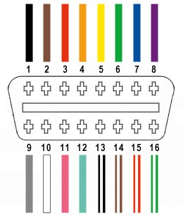
16.1 OBD2 Connector Pinout Basics
The OBD2 connector has 16 pins, each serving a specific function. Here are some of the key pins:
- Pin 4: Chassis Ground
- Pin 5: Signal Ground
- Pin 6: CAN High (J-2284)
- Pin 7: ISO 9141-2 K Line
- Pin 10: SAE J1850 VPW
- Pin 14: CAN Low (J-2284)
- Pin 15: ISO 9141-2 L Line
- Pin 16: Battery Power
16.2 Signal Integrity and Its Importance
Signal integrity refers to the quality of the electrical signal transmitted through the OBD2 cable. A cable with good signal integrity ensures that the data is transmitted accurately and reliably. Factors that can affect signal integrity include:
- Cable Length: Longer cables can experience signal degradation.
- Cable Quality: High-quality cables with proper shielding maintain better signal integrity.
- Connector Quality: Poorly constructed connectors can introduce noise and interference.
- Bend Radius: Exceeding the bend radius can damage the internal wires and shielding, leading to signal loss.
16.3 How Bend Radius Affects Signal Integrity
When an OBD2 cable is bent beyond its recommended bend radius, the internal wires and shielding can be damaged. This damage can lead to:
- Increased Resistance: Damaged wires may have higher resistance, reducing the signal strength.
- Signal Reflection: Imperfections in the cable can cause signals to be reflected back, interfering with the original signal.
- Electromagnetic Interference (EMI): Damaged shielding can allow external electromagnetic waves to interfere with the signal.
16.4 Ensuring Signal Integrity
- Use High-Quality Cables: Invest in OBD2 cables from reputable manufacturers.
- Maintain Proper Bend Radius: Avoid bending the cable beyond its recommended bend radius.
- Avoid Excessive Length: Use the shortest cable length necessary for your application.
- Regular Inspection: Check the cable for any signs of damage.
- Proper Storage: Store the cable in a way that prevents kinking or bending.
17. The Role of Shielding in OBD2 Cables and Its Impact on Diagnostic Accuracy
17.1 What is Shielding?
Shielding in an OBD2 cable refers to the layer of conductive material, usually braided copper or aluminum foil, that surrounds the internal wires. Its primary purpose is to protect the signals transmitted through the cable from electromagnetic interference (EMI) and radio frequency interference (RFI).
17.2 Why Shielding Matters
- Reduces Noise: Shielding minimizes the amount of external noise that can interfere with the diagnostic signals.
- Maintains Signal Integrity: By blocking external interference, shielding helps maintain the integrity of the signals, ensuring accurate data transmission.
- Prevents Data Corruption: Interference can corrupt the data being transmitted, leading to false readings or error codes.
17.3 Types of Shielding
- Foil Shielding: Consists of a thin layer of aluminum foil wrapped around the wires. It provides good coverage but is less durable than braided shielding.
- Braided Shielding: Consists of a woven mesh of copper or aluminum wires. It is more durable and provides better protection against EMI and RFI.
- Combination Shielding: Uses both foil and braided shielding for maximum protection.
17.4 The Impact of Bend Radius on Shielding
- Damage to Shielding: Bending an OBD2 cable beyond its recommended bend radius can damage the shielding layer. This damage can create gaps or breaks in the shielding, reducing its effectiveness.
- Increased Interference: Damaged shielding allows more EMI and RFI to penetrate the cable, leading to signal degradation and inaccurate readings.
- Erratic Data Transmission: The increased interference can cause erratic data transmission, resulting in intermittent connections or false error codes.
17.5 Maintaining Shielding Integrity
- Avoid Over-Bending: Always adhere to the recommended bend radius to prevent damage to the shielding.
- Proper Storage: Store the cable in a loose coil to avoid kinking or bending.
- Regular Inspection: Check the cable for any signs of damage, such as cracks or exposed wires.
- Use Cable Protectors: Consider using cable sleeves or protectors to provide additional protection against physical damage.
18. Using a Multimeter to Test OBD2 Cable Continuity
18.1 What is a Multimeter?
A multimeter is a versatile electronic instrument used to measure voltage, current, and resistance. It is an essential tool for diagnosing electrical problems in vehicles and can also be used to test the continuity of OBD2 cables.
18.2 Why Test Continuity?
Testing the continuity of an OBD2 cable verifies that each wire within the cable is intact and can conduct electricity. This is important because damaged wires can cause intermittent connections or prevent the scanner from communicating with the vehicle’s computer.
18.3 Steps to Test OBD2 Cable Continuity
- Gather Your Tools:
- Multimeter
- OBD2 cable
- OBD2 pinout diagram (to identify the function of each pin)
- Set Up the Multimeter:
- Turn on the multimeter and set it to the continuity testing mode. This mode is usually indicated by a diode symbol or a sound wave symbol.
- Identify the Pins:
- Use the OBD2 pinout diagram to identify the corresponding pins on each end of the cable.
- Test Each Pin:
- Place one probe of the multimeter on a pin at one end of the cable.
- Place the other probe on the corresponding pin at the other end of the cable.
- Observe the multimeter reading. If the multimeter beeps or displays a value close to zero ohms, it indicates that the wire is continuous. If the multimeter displays an open circuit or a very high resistance, it indicates that the wire is broken.
- Repeat for All Pins:
- Repeat the process for all 16 pins to ensure that each wire is intact.
18.4 Interpreting the Results
- Continuous Wires: A beep or a low resistance reading indicates that the wire is continuous and functioning properly.
- Broken Wires: An open circuit or a high resistance reading indicates that the wire is broken and needs to be repaired or replaced.
18.5 Safety Precautions
- Disconnect the Cable: Ensure that the OBD2 cable is disconnected from any power source before testing.
- Use Proper Probes: Use probes with insulated handles to avoid electric shock.
19. Advanced Diagnostics: Using an Oscilloscope to Analyze OBD2 Signals
19.1 What is an Oscilloscope?
An oscilloscope is an electronic instrument that displays electrical signals as a waveform on a screen. It is used to analyze the amplitude, frequency, and shape of the signals, providing detailed information about their characteristics.
19.2 Why Use an Oscilloscope for OBD2 Diagnostics?
- Detailed Signal Analysis: An oscilloscope allows you to examine the signals transmitted through the OBD2 cable in detail, revealing subtle issues that a multimeter cannot detect.
- Detecting Noise and Interference: An oscilloscope can identify noise and interference in the signals, helping you diagnose shielding problems or other signal integrity issues.
- Analyzing Communication Protocols: An oscilloscope can be used to analyze the communication protocols used by the vehicle’s computer, such as CAN, ISO 9141-2, and SAE J1850.
19.3 Steps to Use an Oscilloscope for OBD2 Diagnostics
- Gather Your Tools:
- Oscilloscope
- OBD2 breakout box or adapter
- OBD2 pinout diagram
- Connect the Oscilloscope:
- Connect the oscilloscope probes to the appropriate pins on the OBD2 breakout box or adapter.
- Use the OBD2 pinout diagram to identify the function of each pin.
- Set Up the Oscilloscope:
- Set the oscilloscope to the appropriate voltage and time scales.
- Trigger the oscilloscope to capture the signals.
- Analyze the Signals:
- Observe the waveforms on the oscilloscope screen.
- Look for any abnormalities, such as noise, distortion, or missing signals.
- Compare the signals to known good waveforms to identify any issues.
19.4 Interpreting the Results
- Normal Signals: Clean, well-defined waveforms indicate that the signals are normal.
- Noisy Signals: Noisy waveforms indicate that there is interference in the signals.
- Distorted Signals: Distorted waveforms indicate that there may be a problem with the signal source or the cable.
- Missing Signals: Missing waveforms indicate that there may be a broken wire or a problem with the signal source.
20. Expert Tips for Extending the Life of Your OBD2 Scanner and Cables
20.1 Proper Handling Techniques
- Avoid Dropping: Dropping the scanner or cable can damage the internal components.
- Gentle Connections: When connecting or disconnecting the cable, use gentle pressure to avoid damaging the connector pins.
- Avoid Pulling: Never pull on the cable to disconnect it. Always grasp the connector.
20.2 Regular Cleaning
- Clean Connectors: Use a contact cleaner to clean the connectors regularly.
- Wipe Down Cables: Wipe down the cables with a damp cloth to remove dirt and grime.
20.3 Protective Measures
- Use Protective Cases: Use protective cases for the scanner and cable to prevent damage.
- Cable Sleeves: Use cable sleeves to protect the cable from abrasion and bending.
20.4 Storage Best Practices
- Loose Coils: Store the cable in a loose coil to avoid tight bends.
- Avoid Extreme Temperatures: Avoid storing the scanner and cable in extreme temperatures or direct sunlight.
- Dry Environment: Store the scanner and cable in a dry environment to prevent corrosion.
20.5 Software Updates
- Keep Software Updated: Keep the scanner’s software updated to ensure compatibility and access to the latest features.
20.6 Professional Maintenance
- Regular Checkups: Consider having the scanner and cable professionally inspected and maintained on a regular basis.
Following these expert tips can significantly extend the life of your OBD2 scanner and cables, saving you time and money in the long run.
21. Understanding J1962 Connector Standards for OBD2 Cables
21.1 What is the J1962 Standard?
The J1962 standard, maintained by the Society of Automotive Engineers (SAE), defines the physical characteristics of the diagnostic connector used in vehicles for OBD2 communication. This standard ensures compatibility between diagnostic tools and vehicles across different manufacturers.
21.2 Key Aspects of the J1962 Standard
- Connector Type: Specifies the 16-pin trapezoidal connector.
- Pin Assignments: Defines the function of each pin, including power, ground, and communication lines.
- Electrical Characteristics: Sets the voltage levels and signal characteristics for communication.
- Physical Dimensions: Establishes the size and shape of the connector to ensure proper fit and connection.
21.3 Why the J1962 Standard Matters
- Compatibility: Ensures that any OBD2 scanner can connect to any vehicle that complies with the standard.
- Standardization: Provides a uniform interface for accessing diagnostic data.
- Reliability: Promotes reliable communication between the scanner and the vehicle’s computer.
21.4 Common Issues Related to J1962 Compliance
- Non-Compliant Connectors: Some aftermarket cables may use connectors that do not fully comply with the J1962 standard, leading to poor connections or communication errors.
- Pin Damage: Damaged or bent pins can prevent proper contact, resulting in intermittent connections or complete failure.
- Wiring Issues: Incorrect wiring or poor-quality wires can compromise signal integrity and lead to inaccurate readings.
21.5 Ensuring J1962 Compliance
- Purchase from Reputable Sources: Buy OBD2 cables from reputable manufacturers that adhere to the J1962 standard.
- Inspect the Connector: Check the connector for any signs of damage or non-compliance.
- Test the Cable: Use a multimeter to verify the continuity and proper pin assignments.
22. The Future of Automotive Diagnostics: Beyond OBD2 Cables
22.1 Advancements in Wireless Technology
- Bluetooth OBD2 Adapters: Allow wireless communication between the vehicle and a smartphone or tablet.
- Wi-Fi OBD2 Adapters: Provide a longer range and higher data transfer rates than Bluetooth.
22.2 Cloud-Based Diagnostics
- Remote Diagnostics: Enable technicians to diagnose vehicles remotely, reducing the need for physical connections.
- Data Logging and Analysis: Allow for real-time data logging and analysis, providing valuable insights into vehicle performance.
22.3 Artificial Intelligence (AI) in Diagnostics
- AI-Powered Scanners: Can automatically diagnose complex issues based on historical data and machine learning algorithms.
- Predictive Maintenance: Use AI to predict potential failures before they occur, allowing for proactive maintenance.
22.4 The Role of OBD2 Cables in the Future
While wireless technology and AI are transforming automotive diagnostics, OBD2 cables will likely remain relevant for certain applications, such as:
- Legacy Vehicles: Older vehicles that do not support wireless communication.
- Secure Connections: Situations where a wired connection is preferred for security reasons.
- Data Recovery: Cases where a direct connection is needed to recover data from a damaged ECU.
23. Bend Radius and Cable Management for Heavy-Duty Vehicles
23.1 Unique Challenges in Heavy-Duty Vehicles
- Larger Cables: Heavy-duty vehicles often use thicker OBD2 cables with higher current-carrying capacity.
- Harsh Environments: These vehicles are typically exposed to more extreme conditions, such as vibration, temperature variations, and chemical exposure.
- Complex Wiring Systems: Heavy-duty vehicles have more complex wiring systems, requiring careful cable management.
23.2 Bend Radius Considerations for Heavy-Duty Cables
- Larger Bend Radius: Due to their thickness, heavy-duty OBD2 cables typically have a larger minimum bend radius.
- Material Selection: Cables made with more robust materials, such as polyurethane, are better suited for harsh environments.
- Strain Relief: Proper strain relief is essential to prevent damage to the connector and cable.
23.3 Cable Management Techniques for Heavy-Duty Vehicles
- Secure Routing: Use cable ties, clamps, or conduits to secure the cable and prevent it from rubbing against sharp edges or hot surfaces.
- Avoid Stress Points: Avoid creating tight bends or stress points in the cable.
- Protect from the Elements: Use cable sleeves or protectors to shield the cable from moisture, chemicals, and abrasion.
23.4 Best Practices for Heavy-Duty OBD2 Cables
- Regular Inspection: Inspect the cable regularly for any signs of damage.
- Proper Storage: Store the cable in a loose coil to avoid tight bends.
- Use Quality Cables: Invest in high-quality cables from reputable manufacturers.
24. Integrating OBD2 Data with Mobile Apps and Cloud Platforms
24.1 The Rise of Mobile OBD2 Apps
- Convenience: Mobile apps allow vehicle owners and technicians to access diagnostic data on their smartphones or tablets.
- Real-Time Monitoring: Enable real-time monitoring of vehicle parameters, such as engine temperature, speed, and fuel consumption.
- Data Logging: Allow users to log data and track vehicle performance over time.
24.2 Cloud Integration for Enhanced Diagnostics
- Remote Access: Cloud platforms enable remote access to diagnostic data, allowing technicians to diagnose vehicles from anywhere.
- Data Analysis: Provide advanced data analysis tools for identifying trends and patterns.
- Collaboration: Facilitate collaboration between technicians, allowing them to share data and expertise.
24.3 How OBD2 Cables Fit into the Mobile and Cloud Ecosystem
While wireless OBD2 adapters are becoming increasingly popular, OBD2 cables still play a crucial role in the mobile and cloud ecosystem:
- Initial Setup: Cables may be needed for the initial setup and configuration of wireless adapters.
- Data Recovery: In cases where wireless communication is not possible, a cable can be used to recover data from the vehicle.
- Secure Connections: For certain applications, a wired connection may be preferred for security reasons.
24.4 Best Practices for Using OBD2 Cables with Mobile Apps and Cloud Platforms
- Use Quality Cables: Ensure that you are using high-quality cables that comply with the J1962 standard.
- Maintain Proper Bend Radius: Avoid bending the cable beyond its recommended bend radius.
- Secure Connections: Ensure that the cable is securely connected to the vehicle and the adapter.
25. OBD2 Cable Alternatives: Wireless Adapters and Their Benefits
25.1 What are Wireless OBD2 Adapters?
Wireless OBD2 adapters plug into the vehicle’s OBD2 port and transmit diagnostic data wirelessly to a smartphone, tablet, or computer. These adapters typically use Bluetooth or Wi-Fi technology.
25.2 Benefits of Wireless OBD2 Adapters
- Convenience: Eliminate the need for a physical cable, allowing for greater freedom of movement.
- Compatibility: Compatible with a wide range of devices, including smartphones, tablets, and computers.
- Real-Time Data: Provide real-time data streaming and logging.
- Ease of Use: Simple to set up and use, with user-friendly mobile apps.
25.3 Types of Wireless OBD2 Adapters
- Bluetooth Adapters: Offer a good balance of range and data transfer speed.
- Wi-Fi Adapters: Provide a longer range and higher data transfer rates.
25.4 Limitations of Wireless OBD2 Adapters
- Security Concerns: Wireless communication can be vulnerable to hacking or eavesdropping.
- Compatibility Issues: Some adapters may not be compatible with all vehicles or devices.
- Power Consumption: Wireless adapters can drain the vehicle’s battery if left plugged in for extended periods.
25.5 Choosing the Right Wireless OBD2 Adapter
- Compatibility: Ensure that the adapter is compatible with your vehicle and device.
- Features: Consider the features that are important to you, such as real-time data, data logging, and advanced diagnostics.
- Security: Look for adapters with built-in security features, such as encryption and password protection.
- Reviews: Read reviews from other users to get an idea of the adapter’s performance and reliability.
26. The Impact of OBD2 on Vehicle Maintenance and Repair Costs
26.1 How OBD2 Reduces Maintenance Costs
- Early Detection: OBD2 allows for early detection of potential problems, preventing costly repairs down the road.
- Accurate Diagnostics: Provides accurate diagnostic information, helping technicians identify the root cause of the issue quickly.
- Preventive Maintenance: Enables preventive maintenance, reducing the likelihood of breakdowns.
26.2 How OBD2 Reduces Repair Costs
- Faster Diagnostics: OBD2 helps technicians diagnose issues faster, reducing labor costs.
- Targeted Repairs: Provides specific information about the problem, allowing technicians to perform targeted repairs.
- Reduced Downtime: Minimizes downtime, allowing vehicles to get back on the road quickly.
26.3 The Economic Benefits of OBD2
- Reduced Fuel Consumption: OBD2 can help identify issues that affect fuel consumption, such as a faulty oxygen sensor.
- Extended Vehicle Lifespan: By enabling early detection and preventive maintenance, OBD2 can help extend the lifespan of the vehicle.
- Increased Resale Value: Vehicles with a well-maintained service history typically have a higher resale value.
27. OBD2 and Vehicle Emissions Testing: Ensuring Compliance
27.1 The Role of OBD2 in Emissions Testing
OBD2 plays a crucial role in vehicle emissions testing by monitoring various components and systems that affect emissions. If any of these components or systems are not functioning properly, the OBD2 system will set a diagnostic trouble code (DTC) and illuminate the check engine light.
27.2 OBD2 Monitors and Their Function
- Oxygen Sensor Monitor: Monitors the performance of the oxygen sensors, which are used to measure the amount of oxygen in the exhaust gas.
- Catalyst Monitor: Monitors the efficiency of the catalytic converter, which is used to reduce harmful emissions.
- Evaporative System Monitor: Monitors the evaporative emissions system, which is used to prevent fuel vapors from escaping into the atmosphere.
- EGR System Monitor: Monitors the exhaust gas recirculation (EGR) system, which is used to reduce nitrogen oxide (NOx) emissions.
27.3 Failing an Emissions Test Due to OBD2 Issues
A vehicle may fail an emissions test if the OBD2 system has set a DTC or if the check engine light is illuminated. In some cases, the vehicle may also fail if the OBD2 system is not ready, meaning that the monitors have not completed their tests.
27.4 Ensuring Compliance with Emissions Standards
- Regular Maintenance: Perform regular maintenance to keep the vehicle’s components and systems functioning properly.
- Address DTCs Promptly: Address any DTCs that are set by the OBD2 system promptly.
- Complete Drive Cycles: Complete the necessary drive cycles to allow the OBD2 monitors to complete their tests.
28. Maximizing the Value of Your OBD2 Scanner with Advanced Features
28.1 Live Data Streaming
- Real-Time Monitoring: View real-time data from various sensors and systems in the vehicle.
- Troubleshooting: Use live data to troubleshoot issues and identify the root cause of the problem.
- Performance Analysis: Analyze live data to assess vehicle performance and identify areas for improvement.
28.2 Freeze Frame Data
- Snapshot of Conditions: Capture a snapshot of the vehicle’s operating conditions at the time a DTC was set.
- Diagnostic Assistance: Use freeze frame data to help diagnose the problem.
28.3 On-Board Monitoring Tests
- Detailed Testing: Perform detailed tests of various components and systems in the vehicle.
- Verification: Use on-board monitoring tests to verify that repairs have been successful.
28.4 Bi-Directional Control
- Component Activation: Activate various components in the vehicle to test their functionality.
- Troubleshooting: Use bi-directional control to troubleshoot issues and identify faulty components.
28.5 Software Updates
- Keep Scanner Updated: Keep the scanner’s software updated to ensure compatibility with the latest vehicles and access to the latest features.
29. OBD2 Cable and Scanner Safety: Protecting Yourself and Your Vehicle
29.1 Electrical Safety
- Avoid Water: Keep the scanner and cable away from water and other liquids.
- Proper Grounding: Ensure that the vehicle is properly grounded before connecting the scanner.
- Disconnect Battery: Disconnect the vehicle’s battery before performing any major repairs.
29.2 Vehicle Safety
- Park Vehicle Safely: Park the vehicle in a safe location before performing any diagnostics or repairs.
- Use Wheel Chocks: Use wheel chocks to prevent the vehicle from rolling.
- Wear Safety Glasses: Wear safety glasses to protect your eyes from debris.
29.3 Data Security
- Protect Data: Protect the data stored on the scanner from unauthorized access.
- Secure Connections: Use secure connections when transmitting data wirelessly.
30. OBD2-SCANNER.EDU.VN: Your Partner in Automotive Diagnostics
At OBD2-SCANNER.EDU.VN, we understand the challenges faced by automotive technicians and vehicle owners. That’s why we offer a comprehensive range of resources and services to help