Unlocking your car’s data is easier than you think with an Arduino, a Sparkfun OBD2 adapter, and the right know-how, and OBD2-SCANNER.EDU.VN is here to guide you. Dive in to discover how to read real-time data like RPM and speed and even diagnose potential issues, all while improving your understanding of vehicle diagnostics and repair procedures.
Contents
- 1. Understanding Arduino OBD2 Sparkfun Integration
- 1.1. What is Arduino?
- 1.2. What is OBD2?
- 1.3. What is Sparkfun?
- 1.4. Why Use Arduino with Sparkfun OBD2?
- 2. Essential Components for Your Project
- 2.1. Arduino Board
- 2.2. Sparkfun OBD2 UART Board
- 2.3. LCD Screen
- 2.4. Wiring and Connectors
- 2.5. FTDI Adapter
- 3. Setting Up Your Arduino Environment
- 3.1. Installing the Arduino IDE
- 3.2. Installing Required Libraries
- 3.3. Connecting the Hardware
- 4. Basic Code Structure
- 4.1. Including Libraries
- 4.2. Defining Variables
- 4.3. Setup Function
- 4.4. Loop Function
- 4.5. getResponse Function
- 5. Troubleshooting Common Issues
- 5.1. Data Not Updating
- 5.2. Incorrect Data Readings
- 5.3. Communication Problems
- 5.4. LCD Display Issues
- 5.5. Power Supply Problems
- 6. Advanced Projects and Enhancements
- 6.1. Data Logging
- 6.2. Custom Dashboards
- 6.3. Error Code Interpretation
- 6.4. Integrating Sensors
- 6.5. Wireless Communication
Table of Contents
- Understanding Arduino Obd2 Sparkfun Integration
- What is Arduino?
- What is OBD2?
- What is Sparkfun?
- Why Use Arduino with Sparkfun OBD2?
- Essential Components for Your Project
- Arduino Board
- Sparkfun OBD2 UART Board
- LCD Screen
- Wiring and Connectors
- FTDI Adapter
- Setting Up Your Arduino Environment
- Installing the Arduino IDE
- Installing Required Libraries
- Connecting the Hardware
- Basic Code Structure
- Including Libraries
- Defining Variables
- Setup Function
- Loop Function
getResponseFunction
- Troubleshooting Common Issues
- Data Not Updating
- Incorrect Data Readings
- Communication Problems
- LCD Display Issues
- Power Supply Problems
- Advanced Projects and Enhancements
- Data Logging
- Custom Dashboards
- Error Code Interpretation
- Integrating Sensors
- Wireless Communication
- Safety Precautions
- Electrical Safety
- Vehicle Safety
- Data Security
- The Future of Arduino OBD2 Development
- New Technologies
- Community Contributions
- Educational Opportunities
- FAQ: Frequently Asked Questions
- Need More Help?
1. Understanding Arduino OBD2 Sparkfun Integration
Are you looking to tap into your car’s hidden data using an Arduino OBD2 Sparkfun setup? This combination allows you to read and interpret your vehicle’s diagnostic information, opening up a world of possibilities for monitoring performance and troubleshooting issues. Let’s break down what each component does and why integrating them is so powerful. You’ll gain valuable insights into vehicle diagnostics and potential repair procedures, making you a more informed car owner.
1.1. What is Arduino?
Arduino is an open-source electronics platform based on easy-to-use hardware and software. It’s designed for anyone from artists and hobbyists to students and professionals, making it simple to create interactive electronic projects.
- Microcontroller: At its heart, an Arduino board contains a microcontroller that can be programmed to control various electronic components.
- Open Source: Both the hardware and software are open source, which means you can freely use, modify, and distribute them. This fosters a large community of users and developers who contribute to the platform.
- Easy to Program: The Arduino IDE (Integrated Development Environment) uses a simplified version of C++, making it relatively easy to learn and use.
- Versatile: Arduino can be used for a wide range of projects, from simple LED blinking to complex robotics and data logging.
1.2. What is OBD2?
OBD2 (On-Board Diagnostics II) is a standardized system used in most cars and light trucks manufactured after 1996. It provides access to a wealth of information about your vehicle’s performance and health.
- Diagnostic Data: OBD2 monitors various sensors and systems in your car, such as the engine, transmission, and emissions control systems.
- Error Codes: When a problem is detected, the OBD2 system generates diagnostic trouble codes (DTCs) that can be read using a scanner.
- Standardized Interface: The OBD2 port is a standard 16-pin connector, making it compatible with a wide range of diagnostic tools.
- Real-Time Monitoring: You can use an OBD2 scanner to monitor real-time data, such as engine RPM, vehicle speed, coolant temperature, and oxygen sensor readings.
1.3. What is Sparkfun?
Sparkfun Electronics is a company that provides electronic parts and educational materials to help people learn about electronics. They offer a variety of products, including development boards, sensors, and components.
- Electronic Components: Sparkfun sells a wide range of electronic components, from basic resistors and LEDs to complex sensors and microcontrollers.
- Educational Resources: They provide tutorials, guides, and example code to help users learn how to use their products.
- OBD2 UART Board: Sparkfun’s OBD2 UART board is designed to simplify the process of interfacing with a car’s OBD2 system. It handles the low-level communication protocols, allowing you to focus on reading and interpreting the data.
- User-Friendly: Their products are designed to be user-friendly, making it easier for beginners to get started with electronics.
1.4. Why Use Arduino with Sparkfun OBD2?
Combining Arduino with a Sparkfun OBD2 adapter offers several advantages for vehicle diagnostics and data monitoring.
- Customization: Arduino allows you to create custom solutions tailored to your specific needs. You can design your own dashboards, data loggers, and diagnostic tools.
- Real-Time Data: You can access real-time data from your car’s OBD2 system, allowing you to monitor performance and identify potential issues as they arise.
- Cost-Effective: Building your own OBD2 scanner with Arduino and Sparkfun can be more cost-effective than purchasing a commercial scanner.
- Educational: Working on this type of project is a great way to learn about electronics, programming, and automotive technology.
- Community Support: Both Arduino and Sparkfun have large and active communities of users who can provide support and inspiration for your projects.
By understanding the basics of Arduino, OBD2, and Sparkfun, you’re well-equipped to start building your own vehicle diagnostic and monitoring system. This combination empowers you to take control of your car’s data and gain valuable insights into its performance.
2. Essential Components for Your Project
What hardware do you need for an Arduino OBD2 Sparkfun project? Gathering the right components is the first step to successfully interfacing with your car’s computer. Here’s a detailed list of the essentials. This setup allows you to tap into your car’s data, read real-time information, and diagnose potential issues, making you a more informed and proactive car owner.
2.1. Arduino Board
The Arduino board serves as the brain of your project. It’s responsible for reading data from the OBD2 adapter and displaying it on the LCD screen.
- Arduino Uno: This is a popular choice due to its simplicity and ease of use. It has enough processing power and memory for most OBD2 projects.
- Arduino Mega: If you need more memory or I/O pins, the Mega is a good option. It’s more powerful than the Uno but also more expensive.
- Considerations: Choose a board with sufficient memory and processing power for your project. The Uno is generally sufficient for basic OBD2 data reading, but more complex projects may require the Mega.
2.2. Sparkfun OBD2 UART Board
The Sparkfun OBD2 UART board is the interface between your Arduino and your car’s OBD2 port. It handles the complex communication protocols, making it easier to read data.
- Key Features:
- UART Interface: Communicates with the Arduino using a simple serial interface.
- OBD2 Connector: Plugs directly into your car’s OBD2 port.
- Voltage Regulation: Provides a stable voltage supply for the board.
- Why Sparkfun? Sparkfun provides excellent documentation and support for their products, making it easier to get started.
- Alternatives: Other OBD2 adapters are available, but the Sparkfun board is well-regarded for its reliability and ease of use.
2.3. LCD Screen
An LCD screen is used to display the data read from the OBD2 port.
- 16×2 LCD: A common choice for Arduino projects. It can display two lines of 16 characters each.
- Serial LCD: Simplifies wiring by using a serial interface.
- RGB Backlight: Allows you to customize the display with different colors.
- Considerations: Choose an LCD screen that is easy to read and fits your project’s needs. A 16×2 LCD is a good starting point for most OBD2 projects.
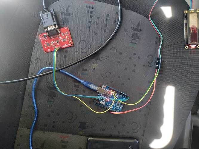
2.4. Wiring and Connectors
Proper wiring is crucial for ensuring that all components communicate correctly.
- Jumper Wires: Used to connect the Arduino, OBD2 adapter, and LCD screen.
- Connectors: May be needed to connect the OBD2 adapter to the car’s OBD2 port.
- Wiring Diagram: Refer to the Sparkfun OBD2 UART Hookup Guide for detailed wiring instructions.
- Essential Connections:
- OBD2 TX -> Arduino RX
- OBD2 RX -> Arduino TX
- OBD2 GND -> Arduino GND
2.5. FTDI Adapter
An FTDI (Future Technology Devices International) adapter is used to communicate between your computer and the Arduino board for programming and debugging.
- USB to TTL: Converts USB signals from your computer to TTL (Transistor-Transistor Logic) signals that the Arduino can understand.
- Debugging: Allows you to monitor the data being sent and received by the Arduino.
- Considerations: Ensure that the FTDI adapter is compatible with your Arduino board. Most Arduino boards use a standard FTDI pinout.
- Alternatives: Some Arduino boards have a built-in USB interface, eliminating the need for an FTDI adapter.
By gathering these essential components, you’ll be well-prepared to start your Arduino OBD2 project. Proper selection and setup of these components will ensure a smooth and successful experience in accessing and interpreting your vehicle’s data.
 Arduino and OBD2 setup for vehicle diagnostics
3. Setting Up Your Arduino Environment
How do you prepare your computer for an Arduino OBD2 Sparkfun project? Setting up your Arduino environment involves installing the necessary software and libraries, which is critical for a successful project. Follow these steps to get everything configured correctly so you can read and interpret your car’s data effectively.
3.1. Installing the Arduino IDE
The Arduino IDE (Integrated Development Environment) is the software used to write, compile, and upload code to your Arduino board.
- Download: Download the latest version of the Arduino IDE from the official Arduino website.
- Installation: Follow the installation instructions for your operating system (Windows, macOS, or Linux).
- Board Selection: After installation, open the Arduino IDE and select your Arduino board from the “Tools > Board” menu.
- Port Selection: Select the correct port for your Arduino board from the “Tools > Port” menu. The port number may vary depending on your operating system.
- Testing: Upload a simple “Blink” sketch to your Arduino board to verify that the IDE is working correctly. This sketch blinks an LED connected to one of the Arduino’s digital pins.
3.2. Installing Required Libraries
Libraries provide pre-written code that simplifies the process of interfacing with hardware components and performing common tasks.
- SoftwareSerial: Allows you to use any of the Arduino’s digital pins for serial communication. This is useful for communicating with the Sparkfun OBD2 UART board.
- DFRobot_RGBLCD: Used to control the DFRobot RGB LCD screen. This library provides functions for initializing the LCD, setting the backlight color, and displaying text.
- Library Manager: Open the Arduino IDE and go to “Sketch > Include Library > Manage Libraries”. Search for the required libraries and install them.
- Manual Installation: If a library is not available in the Library Manager, you can download it from GitHub or another source and install it manually. Place the library folder in the “libraries” folder in your Arduino sketchbook directory.
- Include in Sketch: Include the required libraries in your Arduino sketch using the
#includedirective. For example:
#include <SoftwareSerial.h>
#include <DFRobot_RGBLCD.h>
3.3. Connecting the Hardware
Connecting the hardware correctly is essential for ensuring that all components communicate properly.
- Wiring Diagram: Refer to the Sparkfun OBD2 UART Hookup Guide for detailed wiring instructions.
- Power Supply: Ensure that the Arduino board and other components are properly powered. The Arduino can be powered via USB or an external power supply.
- Grounding: Connect the ground (GND) pins of all components together. This is essential for proper communication and to prevent electrical noise.
- Data Connections: Connect the OBD2 TX pin to the Arduino RX pin and the OBD2 RX pin to the Arduino TX pin. These connections are used for serial communication between the Arduino and the OBD2 adapter.
- LCD Connections: Connect the LCD screen to the Arduino according to the LCD’s documentation. This typically involves connecting several digital pins for data and control signals.
- Double-Check: Double-check all connections before powering on the Arduino. Incorrect wiring can damage the components.
By following these steps, you can set up your Arduino environment and connect the hardware components. This will allow you to start writing code to read data from your car’s OBD2 system and display it on the LCD screen.
4. Basic Code Structure
What’s the basic structure of an Arduino OBD2 Sparkfun code? Understanding the code structure is crucial for reading and interpreting your car’s data. Here’s a breakdown of the essential parts of the Arduino code you’ll be using, allowing you to monitor real-time information such as RPM and speed.
4.1. Including Libraries
Libraries provide pre-written code that simplifies the process of interfacing with hardware components and performing common tasks.
- SoftwareSerial: Allows you to use any of the Arduino’s digital pins for serial communication. This is useful for communicating with the Sparkfun OBD2 UART board.
- DFRobot_RGBLCD: Used to control the DFRobot RGB LCD screen. This library provides functions for initializing the LCD, setting the backlight color, and displaying text.
- Include Directive: Include the required libraries in your Arduino sketch using the
#includedirective. For example:
#include <SoftwareSerial.h>
#include <DFRobot_RGBLCD.h>
4.2. Defining Variables
Variables are used to store data in your Arduino sketch.
- Data Types: Choose appropriate data types for your variables. For example,
intfor integers,charfor characters, andfloatfor floating-point numbers. - Global Variables: Define global variables at the beginning of your sketch. These variables can be accessed from any part of the code.
- Local Variables: Define local variables within functions. These variables can only be accessed from within the function.
- Example:
const int colorR = 255;
const int colorG = 0;
const int colorB = 0;
DFRobot_RGBLCD lcd(16,2);   //16 characters and 2 lines of show
char rxData[20];
char rxIndex=0;
int vehicleSpeed=0;
int vehicleRPM=0;
4.3. Setup Function
The setup() function is called once when the Arduino board starts. It is used to initialize the hardware components and set up the serial communication.
- Serial.begin(): Initializes the serial communication with the specified baud rate.
- lcd.init(): Initializes the LCD screen.
- lcd.setRGB(): Sets the backlight color of the LCD screen.
- lcd.clear(): Clears the LCD screen.
- lcd.print(): Prints text to the LCD screen.
- Example:
void setup() {
lcd.init();
lcd.setRGB(colorR, colorG, colorB);
Serial.begin(9600);
lcd.clear();
lcd.setCursor(0,0);
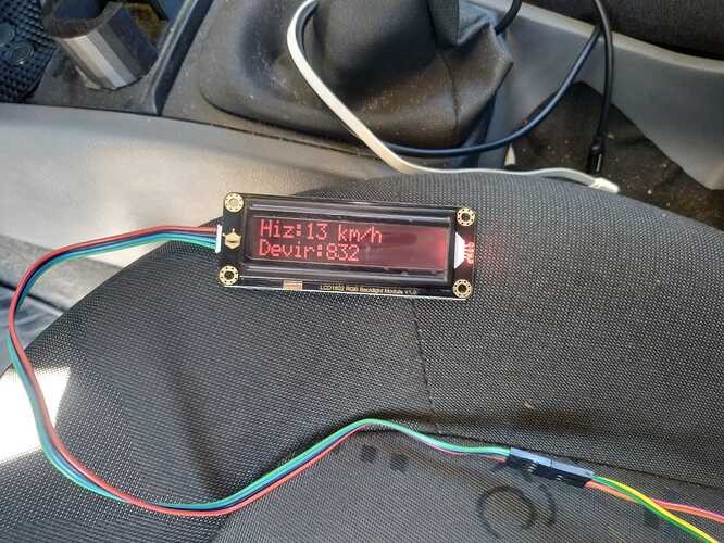
lcd.print("Hiz: ");
lcd.setCursor(0,1);
lcd.print("Devir: ");
delay(1500);
Serial.println("ATZ");
delay(2000);
Serial.flush();
}4.4. Loop Function
The loop() function is called repeatedly after the setup() function has completed. It is used to read data from the OBD2 port, process the data, and display it on the LCD screen.
- Serial.println(): Sends a command to the OBD2 adapter to request data.
- getResponse(): Reads the response from the OBD2 adapter.
- strtol(): Converts a string to a long integer. This is used to convert the data received from the OBD2 adapter to numerical values.
- lcd.setCursor(): Sets the cursor position on the LCD screen.
- lcd.print(): Prints data to the LCD screen.
- delay(): Pauses the program execution for a specified number of milliseconds.
- Example:
void loop() {
  Serial.println("010D");
  getResponse();
  getResponse();
  vehicleSpeed = strtol(&rxData[6],0,16);
  lcd.setCursor(4,0);
  lcd.print(vehicleSpeed);
  lcd.print(" km/h");
  delay(100);
  Serial.flush();
  Serial.println("010C");
  getResponse();
  getResponse();
  vehicleRPM = ((strtol(&rxData[6],0,16)*256)+strtol(&rxData[9],0,16))/4;
  lcd.setCursor(6,1);
  lcd.print(vehicleRPM);
  delay(100);
}
4.5. getResponse Function
The getResponse() function reads data from the serial port until a carriage return character (r) is received.
- Serial.available(): Checks if there is any data available in the serial buffer.
- Serial.peek(): Returns the next character in the serial buffer without removing it.
- Serial.read(): Reads the next character from the serial buffer.
- rxData[]: An array of characters used to store the received data.
- rxIndex: An index used to keep track of the current position in the
rxData[]array. - Example:
void getResponse(void){
  char inChar=0;
  while(inChar != 'r'){
    if(Serial.available() > 0){
      if(Serial.peek() == 'r'){
        inChar=Serial.read();
        rxData[rxIndex]='';
        rxIndex=0;
      }
      else{
        inChar = Serial.read();
        rxData[rxIndex++]=inChar;
      }
    }
  }
}
By understanding the basic code structure, you can start writing your own Arduino sketches to read data from your car’s OBD2 system and display it on the LCD screen.
 Arduino code structure for OBD2 data retrieval
5. Troubleshooting Common Issues
What do you do when your Arduino OBD2 Sparkfun project isn’t working as expected? Troubleshooting is a crucial part of any electronics project. Here are some common issues you might encounter and how to resolve them so you can successfully read and interpret your car’s data.
5.1. Data Not Updating
If the data on your LCD screen isn’t updating, it can be due to several reasons.
- Serial Communication:
- Check Baud Rate: Ensure that the baud rate in your Arduino code matches the baud rate of the Sparkfun OBD2 UART board. The baud rate is typically 9600.
- Wiring: Verify that the RX and TX pins are correctly connected between the Arduino and the OBD2 adapter.
- Serial.flush(): Use
Serial.flush()to clear the serial buffer after sending a command.
- OBD2 Adapter:
- Connection: Make sure the OBD2 adapter is securely plugged into your car’s OBD2 port.
- Power: Verify that the OBD2 adapter is receiving power from the car. Some cars may not provide power to the OBD2 port when the ignition is off.
- Code Issues:
- Command Sequence: Ensure that you are sending the correct OBD2 commands to request data. Refer to the OBD2 documentation for the correct commands.
- getResponse(): Verify that the
getResponse()function is correctly reading data from the serial port.
- Example Fix:
void loop() {
  Serial.println("010D");
  Serial.flush(); // Add this line
  getResponse();
  getResponse();
  vehicleSpeed = strtol(&rxData[6],0,16);
  lcd.setCursor(4,0);
  lcd.print(vehicleSpeed);
  lcd.print(" km/h");
  delay(100);
  Serial.println("010C");
  Serial.flush(); // Add this line
  getResponse();
  getResponse();
  vehicleRPM = ((strtol(&rxData[6],0,16)*256)+strtol(&rxData[9],0,16))/4;
  lcd.setCursor(6,1);
  lcd.print(vehicleRPM);
  delay(100);
}
5.2. Incorrect Data Readings
If the data displayed on your LCD screen is incorrect, it can be due to several factors.
- Data Conversion:
- strtol(): Ensure that you are using the
strtol()function correctly to convert the data received from the OBD2 adapter to numerical values. - Base: Verify that you are specifying the correct base (radix) for the
strtol()function. The base should be 16 for hexadecimal data.
- strtol(): Ensure that you are using the
- OBD2 Commands:
- Correct PID: Ensure that you are using the correct OBD2 PID (Parameter ID) to request data. Refer to the OBD2 documentation for the correct PIDs.
- Data Interpretation: Verify that you are correctly interpreting the data received from the OBD2 adapter. Refer to the OBD2 documentation for the correct data interpretation formulas.
- Code Issues:
- Array Index: Ensure that you are using the correct array index to access the data in the
rxData[]array.
- Array Index: Ensure that you are using the correct array index to access the data in the
- Example Fix:
void loop() {
  Serial.println("010C");
  Serial.flush();
  getResponse();
  getResponse();
  // Corrected RPM calculation
  vehicleRPM = ((strtol(&rxData[3], NULL, 16) * 256) + strtol(&rxData[5], NULL, 16)) / 4;
  lcd.setCursor(6,1);
  lcd.print(vehicleRPM);
  delay(100);
}
5.3. Communication Problems
Communication problems between the Arduino and the OBD2 adapter can prevent data from being read correctly.
- Wiring:
- Loose Connections: Check for loose connections in the wiring between the Arduino and the OBD2 adapter.
- Incorrect Wiring: Verify that the RX and TX pins are correctly connected between the Arduino and the OBD2 adapter.
- Serial Communication:
- Baud Rate: Ensure that the baud rate in your Arduino code matches the baud rate of the Sparkfun OBD2 UART board.
- SoftwareSerial: If you are using the
SoftwareSeriallibrary, ensure that you have initialized it correctly.
- OBD2 Adapter:
- Compatibility: Verify that the OBD2 adapter is compatible with your car. Some OBD2 adapters may not work with all cars.
- Power: Ensure that the OBD2 adapter is receiving power from the car.
- Example Fix:
#include <SoftwareSerial.h>

SoftwareSerial mySerial(10, 11); // RX, TX

void setup() {
  Serial.begin(9600);
  mySerial.begin(9600); // Initialize SoftwareSerial
}

void loop() {
  mySerial.println("010C"); // Send OBD2 command
  delay(50); // Wait for response
  if (mySerial.available() > 0) {
    Serial.print("Response: ");
    Serial.println(mySerial.readStringUntil('r')); // Read and print response
  }
  delay(1000);
}
5.4. LCD Display Issues
Problems with the LCD display can prevent data from being displayed correctly.
- Wiring:
- Loose Connections: Check for loose connections in the wiring between the Arduino and the LCD screen.
- Incorrect Wiring: Verify that the LCD screen is correctly wired to the Arduino.
- Code Issues:
- Library: Ensure that you have installed the correct LCD library for your LCD screen.
- Initialization: Verify that you have initialized the LCD screen correctly in the
setup()function. - Contrast: Adjust the contrast of the LCD screen if the display is too dim or too dark.
- Example Fix:
#include <LiquidCrystal.h>

// Define LCD pins
const int rs = 12, en = 11, d4 = 5, d5 = 4, d6 = 3, d7 = 2;
LiquidCrystal lcd(rs, en, d4, d5, d6, d7);

void setup() {
  lcd.begin(16, 2); // Initialize LCD
  lcd.print("Hello, World!");
}

void loop() {
  // Your code here
}
5.5. Power Supply Problems
Insufficient or unstable power supply can cause various issues with your Arduino project.
- Voltage:
- Check Voltage: Ensure that the Arduino board and other components are receiving the correct voltage.
- External Power Supply: If you are using an external power supply, verify that it is providing a stable voltage.
- Current:
- Insufficient Current: Ensure that the power supply can provide enough current for all components.
- Overload: Avoid overloading the power supply, as this can damage the components.
- Connections:
- Loose Connections: Check for loose connections in the power supply wiring.
- Polarity: Verify that the polarity of the power supply is correct.
- Example Fix: Use a stable 5V power supply with sufficient current to power both the Arduino and the LCD. If using a USB connection, ensure it provides adequate power.
By addressing these common issues, you can troubleshoot your Arduino OBD2 Sparkfun project and get it working correctly. Remember to double-check all connections, verify your code, and consult the documentation for your components.
 Troubleshooting OBD2 Arduino connection issues
6. Advanced Projects and Enhancements
Ready to take your Arduino OBD2 Sparkfun project to the next level? Beyond basic data retrieval, you can create more sophisticated applications that provide deeper insights into your vehicle’s performance. Here are several advanced projects and enhancements to consider, which will give you even greater control over your car’s diagnostics.
6.1. Data Logging
Logging data allows you to record your car’s performance over time, which can be useful for identifying trends and diagnosing intermittent issues.
- SD Card Module: Use an SD card module to store the data on an SD card.
- Real-Time Clock (RTC): Use an RTC module to timestamp the data.
- Data Format: Choose a suitable data format for storing the data, such as CSV or JSON.
- Data Analysis: Use a spreadsheet program or a data analysis tool to analyze the data.
- Example:
#include <SD.h>
#include <SPI.h>
#include <RTClib.h>

// Define SD card pins
const int chipSelect = 10;

// Define RTC object
RTC_DS3231 rtc;

void setup() {
  Serial.begin(9600);

  // Initialize SD card
  Serial.print("Initializing SD card...");
  if (!SD.begin(chipSelect)) {
    Serial.println("SD card initialization failed!");
    while (1);
  }
  Serial.println("SD card initialized.");

  // Initialize RTC
  if (! rtc.begin()) {
    Serial.println("Couldn't find RTC!");
    while (1);
  }

  // Create a new file
  File dataFile = SD.open("data.csv", FILE_WRITE);
  if (dataFile) {
    dataFile.println("Date,Time,RPM,Speed");
    dataFile.close();
  } else {
    Serial.println("Error opening data.csv");
  }
}

void loop() {
  // Get data from OBD2
  int rpm = getRPM();
  int speed = getSpeed();

  // Get current date and time
  DateTime now = rtc.now();
  String date = String(now.year()) + "-" + String(now.month()) + "-" + String(now.day());
  String time = String(now.hour()) + ":" + String(now.minute()) + ":" + String(now.second());

  // Log data to SD card
  File dataFile = SD.open("data.csv", FILE_WRITE);
  if (dataFile) {
    String dataString = date + "," + time + "," + String(rpm) + "," + String(speed);
    dataFile.println(dataString);
    dataFile.close();
    Serial.println("Data logged.");
  } else {
    Serial.println("Error opening data.csv");
  }

  delay(1000);
}

int getRPM() {
  // Your RPM retrieval code here
  return 0; // Replace with actual RPM value
}

int getSpeed() {
  // Your speed retrieval code here
  return 0; // Replace with actual speed value
}
6.2. Custom Dashboards
Create a custom dashboard to display the data in a more user-friendly format.
- Processing: Use Processing, a graphical programming language, to create a custom dashboard on your computer.
- Web Server: Use an Arduino with Ethernet or Wi-Fi capabilities to create a web server that displays the data in a web browser.
- TFT LCD: Use a TFT LCD screen to create a custom dashboard on the Arduino itself.
- Example: Using Processing to create a simple dashboard:
import processing.serial.*;

Serial myPort;  // The serial port

void setup() {
  size(400, 300);
  String portName = Serial.list()[0]; // Change this to your Arduino's port
  myPort = new Serial(this, portName, 9600);
}

void draw() {
  background(0);
  if (myPort.available() > 0) {
    String data = myPort.readStringUntil('n');
    if (data != null) {
      data = trim(data);
      String[] values = split(data, ',');
      if (values.length == 2) {
        float rpm = float(values[0]);
        float speed = float(values[1]);

        // Display RPM
        fill(255);
        textSize(20);
        text("RPM: " + rpm, 20, 30);

        // Display Speed
        text("Speed: " + speed, 20, 60);
      }
    }
  }
}
6.3. Error Code Interpretation
Displaying error codes is useful, but interpreting them can provide even more valuable information.
- DTC Lookup: Create a lookup table that maps DTCs (Diagnostic Trouble Codes) to their corresponding descriptions.
- Online Database: Use an online database to retrieve the descriptions of DTCs.
- Display Description: Display the description of the DTC on the LCD screen or in your custom dashboard.
- Example:
String getErrorDescription(String errorCode) {
  if (errorCode == "P0100") {
    return "Mass Air Flow Circuit Malfunction";
  } else if (errorCode == "P0101") {
    return "Mass Air Flow Circuit Range/Performance Problem";
  } else {
    return "Unknown Error Code";
  }
}
6.4. Integrating Sensors
Adding additional sensors can provide even more data about your car’s performance.
- Temperature Sensors: Monitor the temperature of various components, such as the engine, transmission, and exhaust system.
- Pressure Sensors: Monitor the pressure of various fluids, such as oil, fuel, and coolant.
- Accelerometer: Monitor the acceleration of the car.
- Example: Adding a temperature sensor:
#include <OneWire.h>
#include <DallasTemperature.h>

// Define temperature sensor pins
const int oneWirePin = 2;

// Setup a oneWire instance to communicate with any OneWire devices
OneWire oneWire(oneWirePin);

// Pass our oneWire reference to Dallas Temperature.
DallasTemperature sensors(&oneWire);

void setup() {
  Serial.begin(9600);
  sensors.begin();
}

void loop() {
  // Call sensors.requestTemperatures() to issue a global temperature request to all devices on the bus
  Serial.print("Requesting temperatures...");
  sensors.requestTemperatures();
  Serial.println("DONE");

  // Print temperature in Celsius
  Serial.print("Temperature for the device 1 (C): ");
  Serial.println(sensors.getTempCByIndex(0));

  delay(1000);
}
6.5. Wireless Communication
Adding wireless communication capabilities allows you to monitor your car’s performance remotely.
- Bluetooth: Use a Bluetooth module to transmit the data to a smartphone or computer.
- Wi-Fi: Use a Wi-Fi module to transmit the data to a web server or cloud service.
- GSM: Use a GSM module to transmit the data to a mobile phone.
- Example: Using Bluetooth for wireless communication:
#include <SoftwareSerial.h>

// Define Bluetooth module pins
const int bluetoothTx = 10;
const int bluetoothRx = 11;

// Define SoftwareSerial object
SoftwareSerial bluetoothSerial(bluetoothTx, bluetoothRx);

void setup() {
  Serial.begin(9600);