Are you curious about how many wires are in an OBD2 connector? This comprehensive guide from OBD2-SCANNER.EDU.VN will explore the wiring configuration of OBD2 connectors, their functions, and why understanding them is crucial for automotive diagnostics. Discover the essential information you need to troubleshoot your vehicle effectively.
Contents
- 1. What Is An OBD2 Connector And Its Purpose?
- 1.1. Why Is The OBD2 Connector Important For Automotive Technicians?
- 1.2. How OBD2 Scanners Enhance Diagnostic Accuracy
- 2. The OBD2 Connector: A Detailed Look At Its Physical Structure
- 2.1. Pin Configuration Of The OBD2 Connector
- 2.2. Materials Used In The OBD2 Connector
- 2.3. Common Issues With OBD2 Connector Integrity
- 3. How Many Wires Are Typically Found In An OBD2 Connector?
- 3.1. Standard Wiring Configuration
- 3.2. Variations In Wiring Based On Vehicle Make And Model
- 3.3. Identifying Unused Pins And Their Potential Purposes
- 4. Understanding The Functions Of Each Wire In The OBD2 Connector
- 4.1. Power And Ground Wires
- 4.2. Communication Protocol Wires
- 4.3. Manufacturer-Specific Wires
- 5. Diagnosing Wiring Issues In The OBD2 Connector
- 5.1. Common Symptoms Of A Faulty OBD2 Connector
- 5.2. Tools And Techniques For Testing OBD2 Connector Wires
- 5.3. Step-By-Step Guide To Troubleshooting OBD2 Connector Wiring
- 6. Repairing Damaged Wires In The OBD2 Connector
- 6.1. Necessary Tools And Materials For Wire Repair
- 6.2. Step-By-Step Guide To Replacing A Damaged Wire
- 6.3. Ensuring A Secure And Reliable Connection
- 7. Common OBD2 Connector Problems And Their Solutions
- 7.1. Corrosion Issues
- 7.2. Physical Damage To The Connector
- 7.3. Loose Connections
- 8. Advanced OBD2 Connector Diagnostics
- 8.1. Using An Oscilloscope To Analyze OBD2 Signals
- 8.2. CAN Bus Diagnostics
- 8.3. Using Breakout Boxes For Advanced Testing
- 9. The Future Of OBD2 Connectors And Automotive Diagnostics
- 9.1. OBD3 And Beyond
- 9.2. The Role Of Wireless Technology In Diagnostics
- 9.3. Integration With Smartphone Apps
- 10. Why Choose OBD2-SCANNER.EDU.VN For Your Diagnostic Needs?
- 10.1. Our Expertise And Experience
- 10.2. Comprehensive Resources And Guides
- 10.3. Personalized Support And Consultation
- FAQ: Understanding OBD2 Connectors
- What Is An OBD2 Scanner?
- How Do I Read OBD2 Codes?
- What Are Common OBD2 Error Codes?
- Can I Use An OBD2 Scanner On Any Car?
- How Can I Reset The Check Engine Light Using An OBD2 Scanner?
- What Does Live Data Mean On An OBD2 Scanner?
- Are Wireless OBD2 Scanners Reliable?
- What Should I Do If My OBD2 Scanner Shows No Codes?
- How Often Should I Use An OBD2 Scanner?
- Where Is The OBD2 Port Located In My Car?
1. What Is An OBD2 Connector And Its Purpose?
An OBD2 (On-Board Diagnostics II) connector is a standardized interface used in modern vehicles to access the vehicle’s computer for diagnostics and monitoring. According to the Environmental Protection Agency (EPA), OBD2 became mandatory in all cars sold in the United States in 1996 to standardize emissions testing and provide better diagnostic capabilities.
The primary purposes of the OBD2 connector are to:
- Provide access to a vehicle’s Engine Control Unit (ECU) and other control modules.
- Allow technicians to read Diagnostic Trouble Codes (DTCs) to identify issues.
- Enable real-time data monitoring of various engine parameters.
- Facilitate emission testing and compliance.
- Support reprogramming and software updates for vehicle systems.
1.1. Why Is The OBD2 Connector Important For Automotive Technicians?
For automotive technicians, the OBD2 connector is an indispensable tool. It allows for quick and accurate diagnostics, which can save time and reduce the cost of repairs. As reported by the National Institute for Automotive Service Excellence (ASE), technicians who are proficient in using OBD2 scanners can diagnose issues more efficiently, leading to higher customer satisfaction.
The benefits of using an OBD2 connector include:
- Faster Diagnostics: Quickly identify the source of a problem.
- Accurate Readings: Access real-time data for precise analysis.
- Comprehensive Data: Monitor a wide range of vehicle parameters.
- Standardization: Use a universal interface across different vehicle makes and models.
- Emission Compliance: Ensure vehicles meet environmental regulations.
1.2. How OBD2 Scanners Enhance Diagnostic Accuracy
OBD2 scanners enhance diagnostic accuracy by providing specific Diagnostic Trouble Codes (DTCs) that pinpoint the area of the problem. Modern scanners can also display live data, such as engine temperature, RPM, and sensor readings, allowing technicians to see exactly what is happening in real-time. A study by the Society of Automotive Engineers (SAE) found that using advanced OBD2 scanners can reduce diagnostic time by up to 50%.
The key features that improve diagnostic accuracy are:
- DTC Readout: Provides specific codes that identify the problem area.
- Live Data Streaming: Allows real-time monitoring of engine parameters.
- Freeze Frame Data: Captures data when a DTC is triggered, providing context.
- Graphing Capabilities: Visual representation of data for easier analysis.
- Enhanced Codes: Access to manufacturer-specific codes for deeper diagnostics.
2. The OBD2 Connector: A Detailed Look At Its Physical Structure
The OBD2 connector is a standardized, 16-pin, D-shaped female connector. Its physical structure is designed to ensure a secure and reliable connection between the vehicle’s diagnostic system and external diagnostic tools.
2.1. Pin Configuration Of The OBD2 Connector
The OBD2 connector has 16 pins, each with a specific function. However, not all pins are universally used by every vehicle manufacturer. The Society of Automotive Engineers (SAE) and the International Organization for Standardization (ISO) define the standardized pin assignments.
Here’s a detailed overview of the common pin configurations:
| Pin Number | Description | Common Use |
|---|---|---|
| 1 | Manufacturer Discretion | Varies by manufacturer |
| 2 | SAE J1850 Bus Positive | Ford SCP (Standard Corporate Protocol) |
| 3 | Manufacturer Discretion | Varies by manufacturer |
| 4 | Chassis Ground | Ground connection for the vehicle chassis |
| 5 | Signal Ground | Ground connection for the diagnostic system |
| 6 | CAN High (J-2284) | Controller Area Network high signal |
| 7 | ISO 9141-2 K Line | Communication line for ISO 9141-2 protocol |
| 8 | Manufacturer Discretion | Varies by manufacturer |
| 9 | Manufacturer Discretion | Varies by manufacturer |
| 10 | SAE J1850 Bus Negative | Ford SCP (Standard Corporate Protocol) |
| 11 | Manufacturer Discretion | Varies by manufacturer |
| 12 | Manufacturer Discretion | Varies by manufacturer |
| 13 | Manufacturer Discretion | Varies by manufacturer |
| 14 | CAN Low (J-2284) | Controller Area Network low signal |
| 15 | ISO 9141-2 L Line | Communication line for ISO 9141-2 protocol (rarely used) |
| 16 | Battery Power | Positive voltage supply from the battery |
2.2. Materials Used In The OBD2 Connector
The OBD2 connector is typically made from durable plastic materials that can withstand the harsh conditions of the automotive environment. The pins are made from conductive metals such as copper or brass, which are often coated with gold or tin to prevent corrosion and ensure reliable electrical contact.
Key material considerations include:
- Connector Housing: High-impact plastic resistant to temperature extremes and chemical exposure.
- Pins: Copper or brass alloy with gold or tin plating for conductivity and corrosion resistance.
- Wiring: Automotive-grade wiring with insulation that resists abrasion, heat, and chemicals.
2.3. Common Issues With OBD2 Connector Integrity
Several issues can compromise the integrity of an OBD2 connector, leading to diagnostic problems. Common issues include:
- Corrosion: Exposure to moisture and road salts can corrode the pins, leading to poor electrical contact.
- Pin Damage: Physical damage to the pins, such as bending or breaking, can prevent proper connection.
- Loose Connections: Vibrations and repeated use can loosen the connections between the wires and the pins.
- Wiring Issues: Damaged or frayed wiring can cause intermittent or complete loss of communication.
- Contamination: Dirt, oil, and other contaminants can interfere with the electrical connection.
Regular inspection and maintenance of the OBD2 connector can help prevent these issues and ensure reliable diagnostic performance.
3. How Many Wires Are Typically Found In An OBD2 Connector?
The number of wires in an OBD2 connector can vary depending on the vehicle and the specific functions supported. While the connector has 16 pins, not all of them are always used.
3.1. Standard Wiring Configuration
In a standard configuration, an OBD2 connector will typically have between 4 and 8 wires connected. These wires are essential for basic diagnostic functions, such as reading trouble codes and accessing real-time data.
The commonly used wires include:
- Pin 4: Chassis Ground
- Pin 5: Signal Ground
- Pin 6: CAN High (J-2284)
- Pin 7: ISO 9141-2 K Line
- Pin 14: CAN Low (J-2284)
- Pin 16: Battery Power
3.2. Variations In Wiring Based On Vehicle Make And Model
The wiring configuration can vary significantly between different vehicle makes and models. Some manufacturers use additional pins for proprietary diagnostic functions or to support specific communication protocols.
For example:
- Ford: May use Pin 2 and Pin 10 for SAE J1850 communication.
- GM: May use different pins for specific diagnostic functions.
- European Vehicles: Often utilize the ISO 9141-2 K Line (Pin 7) for communication.
3.3. Identifying Unused Pins And Their Potential Purposes
Identifying unused pins can be useful for understanding the vehicle’s diagnostic capabilities and potential for future upgrades. Unused pins may be reserved for manufacturer-specific functions or for future expansion of the OBD2 system.
To identify the purpose of unused pins:
- Consult the Vehicle’s Service Manual: This provides detailed wiring diagrams and pinout information.
- Use a Pinout Diagram: These diagrams show the standard and manufacturer-specific pin assignments.
- Check Online Resources: Online forums and databases may provide information on specific vehicle models.
4. Understanding The Functions Of Each Wire In The OBD2 Connector
Each wire in the OBD2 connector serves a specific function, enabling different aspects of vehicle diagnostics and communication.
4.1. Power And Ground Wires
The power and ground wires are essential for providing the necessary electrical supply for the OBD2 scanner and the vehicle’s diagnostic system.
- Pin 16 (Battery Power): Provides a direct connection to the vehicle’s battery, supplying 12V power to the OBD2 scanner. This ensures the scanner can operate independently of the vehicle’s ignition system.
- Pin 4 (Chassis Ground): Provides a ground connection to the vehicle’s chassis, ensuring a common ground potential for all electrical components.
- Pin 5 (Signal Ground): Provides a dedicated ground connection for the diagnostic system, reducing electrical noise and ensuring accurate data transmission.
4.2. Communication Protocol Wires
The communication protocol wires enable data transfer between the OBD2 scanner and the vehicle’s ECU. Different vehicles use different communication protocols, and the OBD2 connector supports several standards.
- Pin 2 (SAE J1850 Bus Positive) and Pin 10 (SAE J1850 Bus Negative): Used by Ford and some GM vehicles for SAE J1850 communication, a legacy protocol.
- Pin 7 (ISO 9141-2 K Line) and Pin 15 (ISO 9141-2 L Line): Used by many European and Asian vehicles for ISO 9141-2 communication, another legacy protocol.
- Pin 6 (CAN High (J-2284)) and Pin 14 (CAN Low (J-2284)): Used by most modern vehicles for Controller Area Network (CAN) communication, the current standard.
4.3. Manufacturer-Specific Wires
Some manufacturers use additional pins for proprietary diagnostic functions or to support specific vehicle systems. These wires are not standardized and can vary significantly between different makes and models.
Examples of manufacturer-specific wires include:
- Airbag System Diagnostics: Some manufacturers use specific pins to access the airbag control module.
- ABS System Diagnostics: Other pins may be used to communicate with the Anti-lock Braking System (ABS).
- Transmission Diagnostics: Certain pins can provide access to the transmission control module.
5. Diagnosing Wiring Issues In The OBD2 Connector
Diagnosing wiring issues in the OBD2 connector is crucial for ensuring accurate and reliable diagnostic readings.
5.1. Common Symptoms Of A Faulty OBD2 Connector
Several symptoms can indicate a faulty OBD2 connector:
- No Communication: The OBD2 scanner fails to connect to the vehicle’s ECU.
- Intermittent Connection: The connection is unreliable, with frequent dropouts.
- Incorrect Data: The scanner displays inaccurate or nonsensical data.
- Error Codes: The scanner reports communication errors or other diagnostic issues.
- Physical Damage: Visible damage to the connector, such as broken pins or a cracked housing.
5.2. Tools And Techniques For Testing OBD2 Connector Wires
Several tools and techniques can be used to test the OBD2 connector wires:
- Multimeter: Used to measure voltage, continuity, and resistance in the wires.
- OBD2 Scanner: Used to check for communication errors and read diagnostic data.
- Wiring Diagram: Used to identify the correct pin assignments and wire colors.
- Visual Inspection: Used to check for physical damage, corrosion, and loose connections.
5.3. Step-By-Step Guide To Troubleshooting OBD2 Connector Wiring
Follow these steps to troubleshoot OBD2 connector wiring:
- Visual Inspection: Check the connector for any signs of physical damage, corrosion, or loose connections.
- Check Power and Ground: Use a multimeter to verify that Pin 16 has 12V power and that Pin 4 and Pin 5 have a good ground connection.
- Test Continuity: Use a multimeter to check the continuity of each wire, ensuring there are no breaks or shorts.
- Check Communication Lines: Use an OBD2 scanner to attempt communication with the vehicle’s ECU. If there are communication errors, check the wiring for the CAN High (Pin 6), CAN Low (Pin 14), K Line (Pin 7), and L Line (Pin 15) wires.
- Consult Wiring Diagram: Refer to the vehicle’s wiring diagram to verify the correct pin assignments and wire colors.
6. Repairing Damaged Wires In The OBD2 Connector
Repairing damaged wires in the OBD2 connector can restore proper diagnostic functionality to your vehicle.
6.1. Necessary Tools And Materials For Wire Repair
To repair damaged wires, you will need the following tools and materials:
- Wire Strippers: Used to remove the insulation from the wires.
- Crimping Tool: Used to crimp new connectors onto the wires.
- Soldering Iron: Used to solder the wires together for a secure connection.
- Heat Shrink Tubing: Used to insulate the soldered connections.
- Electrical Tape: Used to provide additional insulation and protection.
- Replacement Connectors: Used to replace damaged or corroded connectors.
- Wiring Diagram: Used to identify the correct wire colors and pin assignments.
6.2. Step-By-Step Guide To Replacing A Damaged Wire
Follow these steps to replace a damaged wire in the OBD2 connector:
- Disconnect the Battery: Disconnect the vehicle’s battery to prevent electrical shock.
- Identify the Damaged Wire: Use a wiring diagram to identify the damaged wire and its pin assignment.
- Remove the Damaged Wire: Use a wire stripper to cut the damaged wire near the connector.
- Prepare the New Wire: Strip the insulation from both ends of the new wire.
- Attach the New Connector: Crimp a new connector onto one end of the new wire, ensuring a secure connection.
- Solder the Wires: Solder the other end of the new wire to the corresponding wire in the vehicle’s wiring harness.
- Insulate the Connection: Use heat shrink tubing to insulate the soldered connection, providing protection from moisture and corrosion.
- Reconnect the Battery: Reconnect the vehicle’s battery and test the OBD2 connector with a scanner to ensure proper functionality.
6.3. Ensuring A Secure And Reliable Connection
To ensure a secure and reliable connection, follow these best practices:
- Use High-Quality Connectors: Use high-quality replacement connectors that are designed for automotive applications.
- Proper Crimping: Use a crimping tool to ensure a secure and reliable crimp connection.
- Proper Soldering: Use a soldering iron to create a strong and durable solder joint.
- Proper Insulation: Use heat shrink tubing to provide adequate insulation and protection from moisture and corrosion.
- Test the Connection: Use a multimeter to verify the continuity of the repaired wire and test the OBD2 connector with a scanner to ensure proper functionality.
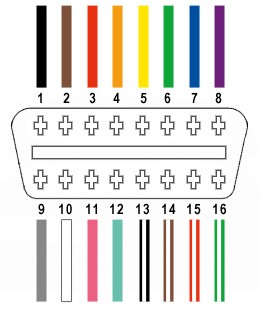 OBD2 Connector Pinout Diagram
7. Common OBD2 Connector Problems And Their Solutions
Addressing common issues can help maintain your vehicle’s diagnostic capabilities.
7.1. Corrosion Issues
Corrosion is a common problem in OBD2 connectors, especially in vehicles that are exposed to moisture and road salts.
Symptoms of Corrosion:
- Difficulty connecting the OBD2 scanner.
- Intermittent connection issues.
- Inaccurate diagnostic readings.
- Visible rust or green buildup on the connector pins.
Solutions for Corrosion:
- Cleaning the Connector: Use a contact cleaner to remove corrosion from the pins. Apply the cleaner to a small brush or cotton swab and gently scrub the pins to remove any buildup.
- Using Dielectric Grease: Apply a small amount of dielectric grease to the pins to prevent future corrosion. Dielectric grease is a non-conductive lubricant that protects electrical connections from moisture and corrosion.
- Replacing the Connector: If the corrosion is severe, replace the entire OBD2 connector. This ensures a reliable connection and prevents further diagnostic issues.
7.2. Physical Damage To The Connector
Physical damage to the OBD2 connector, such as broken pins or a cracked housing, can also cause diagnostic problems.
Symptoms of Physical Damage:
- Broken or bent pins.
- Cracked or damaged connector housing.
- Loose or wobbly connection.
- Inability to connect the OBD2 scanner.
Solutions for Physical Damage:
- Straightening Bent Pins: If the pins are bent, use a small pair of pliers to carefully straighten them. Be gentle to avoid breaking the pins.
- Replacing Damaged Pins: If the pins are broken, they can be replaced using a pin extraction tool. Insert the tool into the connector to release the broken pin, and then insert a new pin in its place.
- Replacing the Connector: If the connector housing is cracked or severely damaged, replace the entire OBD2 connector. This ensures a secure and reliable connection.
7.3. Loose Connections
Loose connections between the wires and the pins in the OBD2 connector can cause intermittent diagnostic problems.
Symptoms of Loose Connections:
- Intermittent connection issues.
- Diagnostic readings that fluctuate or disappear.
- Difficulty maintaining a stable connection with the OBD2 scanner.
Solutions for Loose Connections:
- Tightening the Connections: Use a small screwdriver to gently tighten the screws that hold the wires in place. Be careful not to overtighten the screws, as this can damage the connector.
- Crimping the Connectors: Use a crimping tool to recrimp the connectors onto the wires. This ensures a secure and reliable connection.
- Replacing the Connectors: If the connectors are damaged or corroded, replace them with new connectors. This ensures a stable and reliable connection.
8. Advanced OBD2 Connector Diagnostics
For more complex diagnostic issues, advanced techniques may be required.
8.1. Using An Oscilloscope To Analyze OBD2 Signals
An oscilloscope can be used to analyze the signals transmitted through the OBD2 connector, providing valuable insights into the communication between the scanner and the vehicle’s ECU.
How to Use an Oscilloscope:
- Connect the Oscilloscope: Connect the oscilloscope probes to the appropriate pins on the OBD2 connector. For example, to analyze the CAN bus signals, connect the probes to Pin 6 (CAN High) and Pin 14 (CAN Low).
- Set the Time and Voltage Scales: Adjust the time and voltage scales on the oscilloscope to capture the signals.
- Analyze the Waveforms: Observe the waveforms on the oscilloscope screen. Look for any abnormalities, such as missing signals, distorted signals, or incorrect voltage levels.
Interpreting Oscilloscope Readings:
- CAN Bus Signals: The CAN bus signals should appear as a series of pulses, with a voltage level that fluctuates between 0V and 5V.
- K Line Signals: The K Line signals should appear as a series of pulses, with a voltage level that fluctuates between 0V and 12V.
- Missing Signals: If a signal is missing, check the wiring for breaks or shorts.
- Distorted Signals: If a signal is distorted, check for interference or noise.
- Incorrect Voltage Levels: If the voltage levels are incorrect, check the power and ground connections.
8.2. CAN Bus Diagnostics
The CAN (Controller Area Network) bus is the primary communication protocol used in modern vehicles. Diagnosing CAN bus issues requires specialized tools and techniques.
Common CAN Bus Problems:
- CAN Bus Errors: The OBD2 scanner reports CAN bus errors, such as “CAN bus off” or “CAN bus communication error.”
- Missing ECUs: The OBD2 scanner cannot detect certain ECUs on the CAN bus.
- Intermittent Communication: Communication with the ECUs is unreliable, with frequent dropouts.
CAN Bus Diagnostic Techniques:
- Checking the CAN Bus Resistance: Use a multimeter to measure the resistance between Pin 6 (CAN High) and Pin 14 (CAN Low). The resistance should be approximately 60 ohms. If the resistance is significantly higher or lower, there may be a problem with the CAN bus wiring or termination resistors.
- Using a CAN Bus Analyzer: A CAN bus analyzer is a specialized tool that can monitor the traffic on the CAN bus and identify any errors or conflicts.
- Isolating the Problem: Disconnect the ECUs one by one to isolate the source of the problem. If disconnecting an ECU resolves the issue, the problem is likely with that ECU or its wiring.
8.3. Using Breakout Boxes For Advanced Testing
Breakout boxes are diagnostic tools that provide access to each pin on the OBD2 connector, allowing for advanced testing and analysis.
How to Use a Breakout Box:
- Connect the Breakout Box: Connect the breakout box to the OBD2 connector.
- Connect the Test Leads: Connect the test leads from the multimeter or oscilloscope to the appropriate pins on the breakout box.
- Perform the Tests: Perform the necessary tests, such as measuring voltage, continuity, or resistance.
Benefits of Using a Breakout Box:
- Easy Access to Pins: Provides easy access to each pin on the OBD2 connector.
- Safe Testing: Protects the OBD2 connector from damage during testing.
- Versatile Testing: Allows for a wide range of tests to be performed.
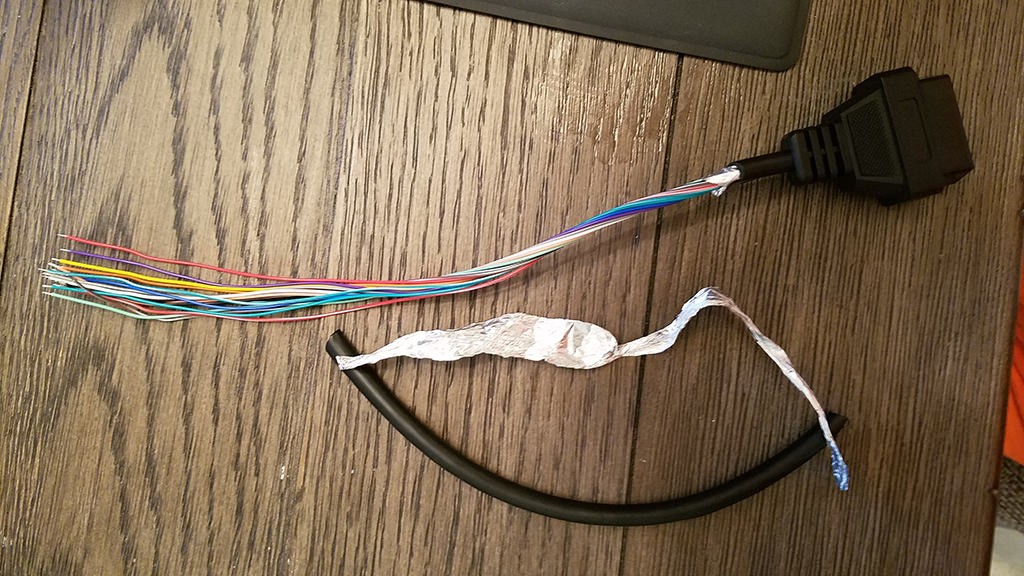 OBD2 Connector
9. The Future Of OBD2 Connectors And Automotive Diagnostics
The OBD2 connector and automotive diagnostics are continuously evolving to meet the demands of modern vehicles.
9.1. OBD3 And Beyond
OBD3 is the next generation of on-board diagnostics, designed to provide more comprehensive and real-time monitoring of vehicle systems.
Key Features of OBD3:
- Real-Time Monitoring: Continuously monitors vehicle systems and reports any issues to the authorities.
- Wireless Communication: Uses wireless communication to transmit diagnostic data to a central database.
- Enhanced Security: Provides enhanced security features to prevent unauthorized access to the vehicle’s diagnostic system.
9.2. The Role Of Wireless Technology In Diagnostics
Wireless technology is playing an increasingly important role in automotive diagnostics, allowing technicians to perform tests and access data remotely.
Benefits of Wireless Diagnostics:
- Remote Access: Technicians can access diagnostic data from anywhere in the world.
- Real-Time Updates: Diagnostic software can be updated in real-time, ensuring that technicians have the latest information.
- Improved Efficiency: Wireless diagnostics can improve efficiency by reducing the time required to perform tests and access data.
9.3. Integration With Smartphone Apps
Smartphone apps are becoming increasingly popular for automotive diagnostics, providing vehicle owners with access to diagnostic data and maintenance information.
Benefits of Smartphone Apps:
- Easy Access: Vehicle owners can easily access diagnostic data and maintenance information from their smartphones.
- Real-Time Alerts: Smartphone apps can provide real-time alerts for any issues with the vehicle.
- Cost Savings: Vehicle owners can save money by performing their own diagnostic tests and maintenance tasks.
10. Why Choose OBD2-SCANNER.EDU.VN For Your Diagnostic Needs?
At OBD2-SCANNER.EDU.VN, we are dedicated to providing you with the most accurate and reliable information on OBD2 connectors and automotive diagnostics. Our team of experienced technicians and automotive experts is committed to helping you understand and troubleshoot your vehicle’s diagnostic system.
10.1. Our Expertise And Experience
We have years of experience in the automotive industry and a deep understanding of OBD2 connectors and diagnostic systems. Our expertise allows us to provide you with the most accurate and up-to-date information on the latest diagnostic techniques and technologies.
10.2. Comprehensive Resources And Guides
We offer a comprehensive range of resources and guides on OBD2 connectors and automotive diagnostics, including:
- Detailed Articles: In-depth articles on OBD2 connector wiring, diagnostic techniques, and troubleshooting tips.
- Step-by-Step Guides: Easy-to-follow guides on how to diagnose and repair common OBD2 connector problems.
- Video Tutorials: Informative video tutorials that demonstrate diagnostic techniques and repair procedures.
- Wiring Diagrams: Detailed wiring diagrams for a wide range of vehicles.
10.3. Personalized Support And Consultation
We offer personalized support and consultation to help you with your specific diagnostic needs. Our team of experts is available to answer your questions and provide guidance on how to troubleshoot your vehicle’s diagnostic system.
Contact Us Today:
- Address: 123 Main Street, Los Angeles, CA 90001, United States
- WhatsApp: +1 (641) 206-8880
- Website: OBD2-SCANNER.EDU.VN
FAQ: Understanding OBD2 Connectors
What Is An OBD2 Scanner?
An OBD2 scanner is a diagnostic tool used to read and interpret data from a vehicle’s On-Board Diagnostics II (OBD2) system, helping identify potential issues.
How Do I Read OBD2 Codes?
To read OBD2 codes, plug the scanner into the OBD2 port, turn on the ignition, and follow the scanner’s prompts to retrieve Diagnostic Trouble Codes (DTCs).
What Are Common OBD2 Error Codes?
Common OBD2 error codes include P0300 (random misfire), P0171 (system too lean), and P0420 (catalyst system efficiency below threshold).
Can I Use An OBD2 Scanner On Any Car?
OBD2 scanners are compatible with most cars and light trucks sold in the United States after 1996, as OBD2 was mandated for all vehicles to standardize emissions testing.
How Can I Reset The Check Engine Light Using An OBD2 Scanner?
After addressing the issue causing the check engine light, use the OBD2 scanner to clear the DTCs, which will reset the light.
What Does Live Data Mean On An OBD2 Scanner?
Live data refers to real-time information from the vehicle’s sensors and systems, allowing you to monitor parameters like engine temperature, RPM, and O2 sensor readings.
Are Wireless OBD2 Scanners Reliable?
Yes, wireless OBD2 scanners, which connect via Bluetooth or Wi-Fi to smartphones or tablets, can be reliable if you choose a reputable brand and ensure a stable connection.
What Should I Do If My OBD2 Scanner Shows No Codes?
If your OBD2 scanner shows no codes, ensure the scanner is properly connected, the ignition is on, and the vehicle supports OBD2. If issues persist, the problem might be with the scanner or the vehicle’s computer.
How Often Should I Use An OBD2 Scanner?
Use an OBD2 scanner whenever the check engine light comes on or if you notice any performance issues with your vehicle to diagnose potential problems early.
Where Is The OBD2 Port Located In My Car?
The OBD2 port is typically located under the dashboard on the driver’s side, but its exact location can vary depending on the vehicle make and model. Consult your owner’s manual for the specific location.
Facing challenges with your vehicle’s diagnostics? Contact OBD2-SCANNER.EDU.VN for expert assistance! Our team is ready to help you understand and resolve any OBD2-related issues. Reach out via WhatsApp at +1 (641) 206-8880 or visit our website at OBD2-SCANNER.EDU.VN for more information. Let us help you keep your vehicle running smoothly and efficiently!