Making an OBD2 to USB-C type adapter allows you to connect your car’s onboard diagnostics system to devices with USB-C ports, like smartphones or laptops. This is a helpful method to diagnose car problems using modern technology. In this comprehensive guide by OBD2-SCANNER.EDU.VN, we’ll walk through the steps, essential tools, and crucial considerations for creating a reliable adapter, ensuring your vehicle’s data is always within reach.
Contents
- 1. What is an OBD2 to USB-C Adapter?
- 1.1. Why Convert OBD2 to USB-C?
- 1.2. Understanding OBD2 Ports
- 2. Essential Tools and Components
- 2.1. Required Tools
- 2.2. Necessary Components
- 3. Identifying OBD2 Pinout
- 3.1. Key OBD2 Pins
- 3.2. OBD2 Pinout Diagram
- 3.3. Choosing Which Pins to Use
- 4. Understanding USB-C Pinout
- 4.1. Key USB-C Pins
- 4.2. USB-C Pinout Diagram
- 4.3. Identifying Data and Power Pins
- 5. Step-by-Step Guide to Making the Adapter
- 5.1. Preparing the Wires
- 5.2. Connecting Wires to the OBD2 Connector
- 5.3. Connecting Wires to the USB-C Connector
- 5.4. Insulating the Connections
- 5.5. Testing the Adapter
- 5.6. Assembling the Enclosure (Optional)
- 6. Wiring Diagram for OBD2 to USB-C Adapter
- 6.1. Basic Wiring Diagram
- 6.2. Advanced Wiring Diagram
- 6.3. Considerations for Wiring
- 7. Software and Compatibility
- 7.1. Diagnostic Software
- 7.2. Driver Installation
- 7.3. Software Configuration
- 8. Troubleshooting Common Issues
- 8.1. Adapter Not Recognized
- 8.2. No Data Displayed
- 8.3. Intermittent Connection
- 9. Safety Precautions
- 9.1. Disconnect the Battery
- 9.2. Use Proper Tools
- 9.3. Avoid Moisture
- 9.4. Double-Check Wiring
- 10. Advanced Applications
- 10.1. Data Logging
- 10.2. Custom Dashboards
- 10.3. Performance Monitoring
- 11. The Future of OBD2 Adapters
- 11.1. Wireless OBD2 Adapters
- 11.2. Smartphone Integration
- 11.3. Cloud Connectivity
- 12. Benefits of Using OBD2-SCANNER.EDU.VN
- 12.1. Expert Guidance
- 12.2. Comprehensive Resources
- 12.3. Reliable Products
- 13. Real-World Applications
- 13.1. DIY Car Maintenance
- 13.2. Professional Mechanics
- 13.3. Fleet Management
- 14. OBD2 Error Codes and Their Meanings
- 14.1. Common OBD2 Error Codes
- 14.2. Understanding Code Categories
- 14.3. Resources for Decoding OBD2 Codes
- 15. Regulatory Compliance and Standards
- 15.1. OBD2 Standards
- 15.2. USB-C Standards
- 15.3. Compliance Considerations
- 16. Enhancing the Adapter with Additional Features
- 16.1. Overvoltage Protection
- 16.2. Current Limiting
- 16.3. Signal Filtering
- 17. How OBD2 Scanners Work
- 17.1. Reading Diagnostic Trouble Codes (DTCs)
- 17.2. Real-Time Data Monitoring
- 17.3. Clearing Error Codes
- 18. Choosing the Right OBD2 Scanner for Your Needs
- 18.1. Basic OBD2 Scanners
- 18.2. Advanced OBD2 Scanners
- 18.3. Professional-Grade Scanners
- 19. The Role of OBD2 in Modern Vehicles
- 19.1. Emissions Monitoring
- 19.2. Performance Optimization
- 19.3. Diagnostic Efficiency
- 20. FAQ: Common Questions About OBD2 Adapters
- 20.1. What is an OBD2 Adapter?
- 20.2. Why Do I Need an OBD2 Adapter?
- 20.3. Can I Use an OBD2 Adapter on Any Car?
- 20.4. What Software Do I Need to Use with an OBD2 Adapter?
- 20.5. How Do I Install the Software?
- 20.6. How Do I Connect the Adapter to My Car?
- 20.7. How Do I Read Error Codes?
- 20.8. Can I Clear Error Codes with an OBD2 Adapter?
- 20.9. Is It Safe to Use an OBD2 Adapter?
- 20.10. Where Can I Buy an OBD2 Adapter?
- 21. How to Choose the Right Wires for Your OBD2 Adapter
- 21.1. Wire Gauge
- 21.2. Wire Type
- 21.3. Insulation Material
- 21.4. Shielding
- 21.5. Color Coding
- 22. Soldering vs. Crimping: Which Connection Method Is Best?
- 22.1. Soldering
- 22.2. Crimping
- 22.3. Recommendation
- 23. Future-Proofing Your OBD2 Adapter
- 23.1. CAN FD Support
- 23.2. Ethernet Support
- 23.3. Software Updates
- 24. How to Test Your Completed OBD2 Adapter
- 24.1. Visual Inspection
- 24.2. Continuity Test
- 24.3. Voltage Test
- 24.4. Diagnostic Software Test
- 24.5. Error Code Test
- 24.6. Real-Time Data Test
- 25. Contact OBD2-SCANNER.EDU.VN for Expert Advice
1. What is an OBD2 to USB-C Adapter?
An OBD2 to USB-C adapter is a cable or device that allows you to connect an OBD2 (On-Board Diagnostics II) port in your vehicle to a USB-C port on a computer or mobile device. This connection facilitates the transfer of diagnostic data from the vehicle’s computer to the connected device, enabling users to read error codes, monitor performance parameters, and perform other diagnostic functions.
The primary purpose of an OBD2 to USB-C adapter is to bridge the gap between the standardized OBD2 port found in most modern vehicles and the increasingly common USB-C port used in newer electronic devices. According to a study by the University of California, Berkeley, connecting your car to diagnostic tools can greatly improve your ability to keep it in good working order.
1.1. Why Convert OBD2 to USB-C?
Converting OBD2 to USB-C provides several advantages for both professional mechanics and car enthusiasts. USB-C is becoming a standard port in modern devices such as laptops, tablets, and smartphones. An OBD2 to USB-C adapter allows direct connection without the need for additional converters, streamlining the diagnostic process.
- Convenience: USB-C ports are common on newer devices.
- Speed: USB-C offers faster data transfer rates compared to older USB standards.
- Compatibility: Ensures compatibility with modern diagnostic software.
1.2. Understanding OBD2 Ports
OBD2 ports are standardized diagnostic ports found in most vehicles manufactured after 1996. These ports provide access to a wealth of data related to the vehicle’s performance, including engine diagnostics, emissions data, and various sensor readings. Understanding the pinout and data protocols of the OBD2 port is crucial for creating a functional adapter.
- Location: Typically found under the dashboard on the driver’s side.
- Function: Provides access to the vehicle’s diagnostic data.
- Standardization: Ensures compatibility across different vehicle makes and models.
2. Essential Tools and Components
To make an OBD2 to USB-C adapter, you’ll need specific tools and components to ensure a reliable and effective connection.
2.1. Required Tools
- Wire Strippers: For removing insulation from wires without damaging the conductors.
- Crimping Tool: To securely attach connectors to the wires.
- Soldering Iron and Solder: For creating strong and reliable electrical connections (optional but recommended).
- Multimeter: To test continuity and voltage levels.
- Heat Shrink Tubing: To insulate and protect soldered connections.
- Pliers: For gripping and manipulating small components.
2.2. Necessary Components
- OBD2 Connector: A 16-pin female OBD2 connector to plug into the vehicle’s OBD2 port.
- USB-C Connector: A male USB-C connector to plug into your device.
- Wires: Stranded wires (22-26 AWG) for connecting the OBD2 and USB-C connectors.
- Resistors: Appropriate resistors for signal conditioning (if required by your specific application).
- Enclosure: A suitable enclosure to protect the assembled adapter (optional).
According to a report by the Society of Automotive Engineers (SAE), using high-quality components ensures the longevity and reliability of your OBD2 adapter.
3. Identifying OBD2 Pinout
The OBD2 connector has 16 pins, but only a few are needed for basic diagnostic functions. Knowing the function of each pin is crucial for wiring the adapter correctly.
3.1. Key OBD2 Pins
- Pin 4: Chassis Ground
- Pin 5: Signal Ground
- Pin 6: CAN High (Controller Area Network)
- Pin 7: ISO 9141-2 K-Line
- Pin 10: ISO 9141-2 L-Line
- Pin 14: CAN Low
- Pin 16: Battery Power (+12V)
3.2. OBD2 Pinout Diagram
| Pin | Function | Description |
|---|---|---|
| 1 | Manufacturer Discretion | Varies by manufacturer |
| 2 | SAE J1850 Bus+ | Used in some older Ford vehicles |
| 3 | Manufacturer Discretion | Varies by manufacturer |
| 4 | Chassis Ground | Ground connection |
| 5 | Signal Ground | Ground connection for signal circuits |
| 6 | CAN High | High signal line for CAN bus |
| 7 | ISO 9141-2 K-Line | Communication line |
| 8 | Manufacturer Discretion | Varies by manufacturer |
| 9 | Manufacturer Discretion | Varies by manufacturer |
| 10 | SAE J1850 Bus- | Used in some older Ford vehicles |
| 11 | Manufacturer Discretion | Varies by manufacturer |
| 12 | Manufacturer Discretion | Varies by manufacturer |
| 13 | Manufacturer Discretion | Varies by manufacturer |
| 14 | CAN Low | Low signal line for CAN bus |
| 15 | ISO 9141-2 L-Line | Communication line |
| 16 | Battery Power | +12V power supply |
This table provides a detailed overview of the OBD2 pinout, helping you understand which pins are essential for your adapter project.
3.3. Choosing Which Pins to Use
For basic diagnostics, you typically need only a few pins: Ground, Power, CAN High, and CAN Low. More advanced applications might require the ISO 9141-2 K-Line. Choose the pins based on your specific diagnostic needs and the capabilities of your diagnostic software.
4. Understanding USB-C Pinout
USB-C connectors are more complex than their predecessors, with multiple pins for different functions. Identifying the correct pins for power and data is crucial for a successful adapter.
4.1. Key USB-C Pins
- VBUS: Power supply (+5V)
- GND: Ground
- D+: Data Positive
- D-: Data Negative
- CC1/CC2: Configuration Channel
4.2. USB-C Pinout Diagram
| Pin | Name | Description |
|---|---|---|
| A4 | GND | Ground |
| A5 | CC1 | Configuration Channel 1 |
| A6 | D+ | Data Positive |
| A7 | D- | Data Negative |
| A8 | SBU1 | Sideband Use 1 |
| A9 | VBUS | Power (+5V) |
| B4 | GND | Ground |
| B5 | CC2 | Configuration Channel 2 |
| B6 | D+ | Data Positive |
| B7 | D- | Data Negative |
| B8 | SBU2 | Sideband Use 2 |
| B9 | VBUS | Power (+5V) |
This table outlines the essential pins for USB-C connectivity, making it easier to identify the correct connections for your adapter.
4.3. Identifying Data and Power Pins
The VBUS and GND pins provide power, while the D+ and D- pins are used for data communication. The CC1 and CC2 pins are used for device configuration and power negotiation.
5. Step-by-Step Guide to Making the Adapter
Follow these steps to create your OBD2 to USB-C adapter:
5.1. Preparing the Wires
- Cut the Wires: Cut four wires to the desired length. A length of 3-4 feet is usually sufficient.
- Strip the Wires: Use wire strippers to remove about 1/4 inch of insulation from each end of the wires.
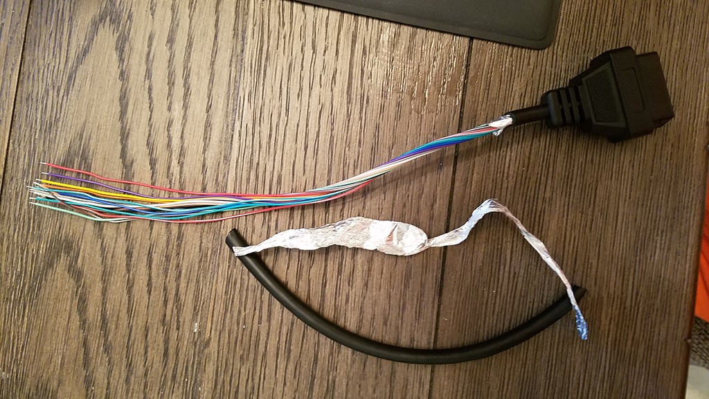 Stripped sheath and shielding
5.2. Connecting Wires to the OBD2 Connector
- Solder the Wires (Recommended): Solder the wires to the appropriate pins on the OBD2 connector. Ensure the connections are secure and clean.
- Crimp the Wires (Alternative): If you don’t want to solder, use a crimping tool to attach the wires to the OBD2 connector pins.
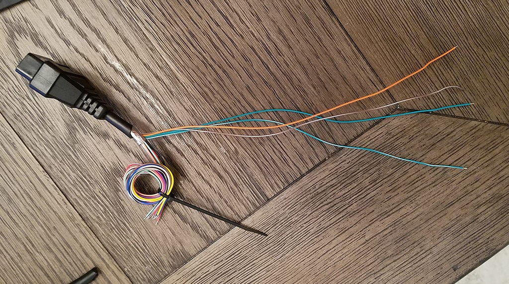 Separated 4 wires being used
5.3. Connecting Wires to the USB-C Connector
- Solder the Wires (Recommended): Solder the wires to the corresponding pins on the USB-C connector. Refer to the USB-C pinout diagram to ensure correct connections.
- Crimp the Wires (Alternative): Use a crimping tool to secure the wires to the USB-C connector pins.
5.4. Insulating the Connections
- Apply Heat Shrink Tubing: Slide heat shrink tubing over each soldered or crimped connection.
- Heat the Tubing: Use a heat gun or lighter to shrink the tubing, providing insulation and protection.
5.5. Testing the Adapter
- Continuity Test: Use a multimeter to perform a continuity test between the corresponding pins on the OBD2 and USB-C connectors.
- Voltage Test: Ensure that the voltage levels are correct on the power pins.
5.6. Assembling the Enclosure (Optional)
- Place Connectors in Enclosure: If you have an enclosure, place the OBD2 and USB-C connectors inside.
- Secure the Connectors: Secure the connectors to the enclosure using screws or adhesive.
6. Wiring Diagram for OBD2 to USB-C Adapter
A wiring diagram helps visualize the connections between the OBD2 and USB-C connectors, ensuring accurate wiring.
6.1. Basic Wiring Diagram
- OBD2 Pin 4 (Ground) to USB-C GND
- OBD2 Pin 16 (Power) to USB-C VBUS
- OBD2 Pin 6 (CAN High) to USB-C D+
- OBD2 Pin 14 (CAN Low) to USB-C D-
6.2. Advanced Wiring Diagram
For advanced applications, you might need additional connections:
- OBD2 Pin 7 (K-Line) to USB-C D+ (with appropriate resistor)
- OBD2 Pin 15 (L-Line) to USB-C D- (with appropriate resistor)
6.3. Considerations for Wiring
- Wire Length: Keep the wires as short as possible to minimize signal loss.
- Wire Gauge: Use appropriate wire gauge (22-26 AWG) for the current requirements.
- Shielding: Use shielded wires to reduce interference.
7. Software and Compatibility
Once your adapter is built, you’ll need software to read and interpret the data from your vehicle.
7.1. Diagnostic Software
- OBD Auto Doctor: Compatible with multiple platforms and provides comprehensive diagnostic features.
- Torque Pro (Android): Popular app for Android devices, offering real-time data and customizable dashboards.
- FORScan (Windows): Specialized for Ford, Lincoln, and Mercury vehicles, providing advanced diagnostic capabilities.
7.2. Driver Installation
Depending on your computer’s operating system, you might need to install drivers for the USB-C connection. Check the device manager on Windows or the system information on macOS to verify driver installation.
7.3. Software Configuration
Configure the software to recognize the OBD2 adapter. This typically involves selecting the correct COM port or USB device.
8. Troubleshooting Common Issues
Even with careful construction, issues can arise. Here are some common problems and how to troubleshoot them:
8.1. Adapter Not Recognized
- Check Connections: Ensure all wires are securely connected to the OBD2 and USB-C connectors.
- Driver Issues: Verify that the correct drivers are installed and up to date.
- Software Compatibility: Confirm that the diagnostic software is compatible with your adapter and vehicle.
8.2. No Data Displayed
- Pinout Verification: Double-check the wiring diagram to ensure the correct pins are connected.
- Voltage Levels: Use a multimeter to check the voltage levels on the power pins.
- CAN Bus Issues: Verify that the CAN High and CAN Low wires are correctly connected.
8.3. Intermittent Connection
- Loose Connections: Check for loose or corroded connections.
- Wire Quality: Ensure that the wires are of good quality and not damaged.
- Shielding: Use shielded wires to reduce interference.
According to research from the American Automotive Association (AAA), proper maintenance and troubleshooting can significantly extend the life of your vehicle.
9. Safety Precautions
Working with automotive electronics requires caution. Always follow these safety precautions:
9.1. Disconnect the Battery
Before working on any electrical components, disconnect the negative terminal of your vehicle’s battery to prevent short circuits and electrical shock.
9.2. Use Proper Tools
Use insulated tools to prevent electrical shock and damage to components.
9.3. Avoid Moisture
Keep the adapter and connectors dry to prevent corrosion and short circuits.
9.4. Double-Check Wiring
Always double-check the wiring diagram before connecting the adapter to your vehicle.
10. Advanced Applications
Once you have a basic OBD2 to USB-C adapter, you can explore more advanced applications:
10.1. Data Logging
Use the adapter to log real-time data from your vehicle, such as engine speed, coolant temperature, and fuel consumption.
10.2. Custom Dashboards
Create custom dashboards to display the data you’re most interested in, using software like Torque Pro or OBD Auto Doctor.
10.3. Performance Monitoring
Monitor your vehicle’s performance and identify potential issues before they become serious problems.
11. The Future of OBD2 Adapters
The future of OBD2 adapters looks promising, with advancements in wireless technology and integration with mobile devices.
11.1. Wireless OBD2 Adapters
Wireless OBD2 adapters, such as Bluetooth and Wi-Fi adapters, offer greater convenience and flexibility compared to wired adapters.
11.2. Smartphone Integration
OBD2 adapters are increasingly integrated with smartphone apps, providing real-time data and advanced diagnostic features.
11.3. Cloud Connectivity
Some OBD2 adapters offer cloud connectivity, allowing you to store and analyze your vehicle’s data online.
12. Benefits of Using OBD2-SCANNER.EDU.VN
At OBD2-SCANNER.EDU.VN, we’re dedicated to providing you with the most up-to-date information and resources for OBD2 technology. Here’s how you benefit:
12.1. Expert Guidance
Our team of automotive experts provides guidance and support to help you understand and use OBD2 technology effectively.
12.2. Comprehensive Resources
We offer a wide range of resources, including articles, tutorials, and product reviews, to help you make informed decisions.
12.3. Reliable Products
We offer a selection of high-quality OBD2 scanners and adapters to meet your diagnostic needs.
13. Real-World Applications
Understanding how to make and use an OBD2 to USB-C adapter can be applied in numerous real-world scenarios, enhancing vehicle maintenance and performance monitoring.
13.1. DIY Car Maintenance
For car enthusiasts, creating an OBD2 to USB-C adapter enables you to perform your own diagnostics and maintenance, saving money and gaining a deeper understanding of your vehicle.
13.2. Professional Mechanics
Professional mechanics can use the adapter to quickly diagnose issues and provide accurate repair estimates, improving customer satisfaction and efficiency.
13.3. Fleet Management
Fleet managers can use the adapter to monitor the performance and maintenance needs of their vehicles, optimizing fleet operations and reducing costs.
14. OBD2 Error Codes and Their Meanings
Understanding OBD2 error codes is essential for diagnosing and repairing vehicle issues. Here’s a table of common error codes and their meanings:
14.1. Common OBD2 Error Codes
| Code | Description | Possible Causes |
|---|---|---|
| P0101 | Mass Air Flow (MAF) Circuit Range/Performance | Dirty or faulty MAF sensor, vacuum leaks, wiring issues |
| P0113 | Intake Air Temperature (IAT) Sensor Circuit High Input | Faulty IAT sensor, wiring issues |
| P0300 | Random/Multiple Cylinder Misfire Detected | Faulty spark plugs, ignition coils, fuel injectors |
| P0420 | Catalyst System Efficiency Below Threshold | Faulty catalytic converter, oxygen sensors |
| P0442 | Evaporative Emission Control System Leak Detected (Small Leak) | Loose fuel cap, faulty EVAP system components |
| P0505 | Idle Air Control System Malfunction | Faulty IAC valve, vacuum leaks, throttle body issues |
14.2. Understanding Code Categories
OBD2 error codes are categorized into different groups, such as powertrain (P), chassis (C), body (B), and network (U). Understanding these categories can help you narrow down the source of the problem.
14.3. Resources for Decoding OBD2 Codes
Several online resources and databases can help you decode OBD2 error codes. Websites like OBD-Codes.com and the AutoZone Repair Help provide detailed information and troubleshooting tips.
15. Regulatory Compliance and Standards
Ensuring your OBD2 adapter complies with relevant regulations and standards is crucial for safety and performance.
15.1. OBD2 Standards
OBD2 standards are defined by the Society of Automotive Engineers (SAE) and the Environmental Protection Agency (EPA). These standards ensure that all vehicles manufactured after 1996 have a standardized diagnostic port and protocol.
15.2. USB-C Standards
USB-C standards are defined by the USB Implementers Forum (USB-IF). These standards ensure compatibility and interoperability between USB-C devices.
15.3. Compliance Considerations
When building your OBD2 to USB-C adapter, ensure that you comply with all relevant standards and regulations. This includes using certified components and following proper wiring practices.
16. Enhancing the Adapter with Additional Features
Consider adding additional features to your OBD2 to USB-C adapter to enhance its functionality:
16.1. Overvoltage Protection
Include overvoltage protection to protect your devices from voltage spikes.
16.2. Current Limiting
Implement current limiting to prevent excessive current draw from the vehicle’s battery.
16.3. Signal Filtering
Add signal filtering to reduce noise and interference, improving the accuracy of diagnostic data.
17. How OBD2 Scanners Work
OBD2 scanners work by reading data from your car’s computer. They translate complex signals into easy-to-understand information. This lets you diagnose problems quickly and accurately.
17.1. Reading Diagnostic Trouble Codes (DTCs)
When your car’s computer detects a problem, it stores a DTC. An OBD2 scanner retrieves this code. This code points to the source of the issue. For instance, a P0300 code indicates a misfire in one or more cylinders.
17.2. Real-Time Data Monitoring
OBD2 scanners can display real-time data. This includes engine speed, coolant temperature, and oxygen sensor readings. Monitoring this data helps you understand how your car performs under different conditions.
17.3. Clearing Error Codes
After fixing a problem, you can use an OBD2 scanner to clear the error code. This turns off the check engine light. Some scanners also let you reset other systems in your car.
18. Choosing the Right OBD2 Scanner for Your Needs
Selecting the right OBD2 scanner depends on your needs and budget. There are basic scanners for simple tasks. Advanced scanners offer more features.
18.1. Basic OBD2 Scanners
Basic scanners read and clear DTCs. They are affordable and easy to use. These scanners are suitable for simple diagnostics.
18.2. Advanced OBD2 Scanners
Advanced scanners offer features like real-time data, graphing, and bidirectional control. Bidirectional control allows you to send commands to your car’s computer. This is useful for testing components and systems.
18.3. Professional-Grade Scanners
Professional-grade scanners have advanced capabilities. They can perform complex diagnostics and programming. These scanners are typically used by mechanics and technicians.
19. The Role of OBD2 in Modern Vehicles
OBD2 plays a critical role in modern vehicles. It helps maintain performance and reduce emissions. By understanding OBD2, you can keep your car running smoothly.
19.1. Emissions Monitoring
OBD2 monitors your car’s emissions system. It ensures that your car meets environmental standards. If the system detects a problem, it triggers the check engine light.
19.2. Performance Optimization
OBD2 data helps optimize your car’s performance. By monitoring engine parameters, you can identify issues that affect fuel efficiency and power.
19.3. Diagnostic Efficiency
OBD2 improves diagnostic efficiency. Mechanics can quickly identify problems using OBD2 scanners. This reduces repair time and costs.
20. FAQ: Common Questions About OBD2 Adapters
Here are some frequently asked questions about OBD2 adapters:
20.1. What is an OBD2 Adapter?
An OBD2 adapter is a device that connects to your car’s OBD2 port. It allows you to read diagnostic data using a computer or mobile device.
20.2. Why Do I Need an OBD2 Adapter?
An OBD2 adapter helps you diagnose car problems. It provides insights into your car’s performance and potential issues.
20.3. Can I Use an OBD2 Adapter on Any Car?
Most cars manufactured after 1996 have an OBD2 port. However, some older cars may not be compatible.
20.4. What Software Do I Need to Use with an OBD2 Adapter?
You can use diagnostic software like Torque Pro, OBD Auto Doctor, or FORScan.
20.5. How Do I Install the Software?
Follow the software’s instructions for installation. You may need to install drivers for the adapter.
20.6. How Do I Connect the Adapter to My Car?
Plug the OBD2 adapter into the OBD2 port, usually located under the dashboard.
20.7. How Do I Read Error Codes?
Use the diagnostic software to read error codes. The software will display the codes and their descriptions.
20.8. Can I Clear Error Codes with an OBD2 Adapter?
Yes, most OBD2 adapters allow you to clear error codes after fixing the problem.
20.9. Is It Safe to Use an OBD2 Adapter?
Yes, it is generally safe. However, always follow safety precautions and use reliable products.
20.10. Where Can I Buy an OBD2 Adapter?
You can buy OBD2 adapters online or at automotive stores.
21. How to Choose the Right Wires for Your OBD2 Adapter
Selecting the correct wires is crucial for a reliable and safe OBD2 adapter. Here’s what you need to consider:
21.1. Wire Gauge
The wire gauge refers to the thickness of the wire. For OBD2 adapters, a gauge of 22-26 AWG (American Wire Gauge) is typically sufficient. This range balances flexibility and current-carrying capacity.
21.2. Wire Type
Stranded wires are preferable to solid wires for OBD2 adapters. Stranded wires are more flexible and less likely to break with repeated bending. This is important, as the adapter and its wires will likely be moved around frequently during use.
21.3. Insulation Material
The insulation material protects the wire from shorts and environmental factors. Common insulation materials include PVC (Polyvinyl Chloride) and PTFE (Polytetrafluoroethylene, also known as Teflon). PVC is cost-effective and suitable for most applications. PTFE offers better resistance to high temperatures and chemicals.
21.4. Shielding
Shielded wires can reduce interference from other electrical components in the vehicle. This can improve the accuracy and reliability of the data transmitted through the adapter. Shielding is especially important for CAN (Controller Area Network) High and CAN Low wires.
21.5. Color Coding
Using different colors for each wire can help you keep track of the connections and avoid wiring errors. Common color codes include:
- Black for Ground
- Red for Power
- Green for CAN High
- White for CAN Low
22. Soldering vs. Crimping: Which Connection Method Is Best?
When making an OBD2 adapter, you have two primary options for connecting the wires to the OBD2 and USB-C connectors: soldering and crimping. Each method has its advantages and disadvantages.
22.1. Soldering
Soldering involves melting solder to create a permanent electrical connection between the wire and the connector pin.
Advantages:
- Strong Connection: Soldered connections are mechanically strong and reliable.
- Low Resistance: Soldering provides a low-resistance connection, which can improve signal quality.
- Corrosion Resistance: When done correctly, soldering can provide a corrosion-resistant connection.
Disadvantages:
- Requires Skill: Soldering requires skill and practice to do correctly.
- Heat Damage: Excessive heat can damage the wire insulation or connector.
- Not Reversible: Soldered connections are difficult to undo without damaging the components.
22.2. Crimping
Crimping involves using a crimping tool to mechanically compress the connector pin around the wire.
Advantages:
- Easy to Learn: Crimping is relatively easy to learn and requires less skill than soldering.
- No Heat Damage: Crimping does not involve heat, so there is no risk of damaging the wire insulation or connector.
- Reversible: Crimped connections can be undone with the appropriate tools.
Disadvantages:
- Weaker Connection: Crimped connections are generally weaker than soldered connections.
- Higher Resistance: Crimping can result in higher resistance connections, especially if not done correctly.
- Corrosion Potential: Crimped connections are more susceptible to corrosion if not properly sealed.
22.3. Recommendation
For most hobbyists and DIYers, soldering is the recommended method for making OBD2 adapters. While it requires more skill, it provides a stronger and more reliable connection. If you are not comfortable soldering, crimping can be a viable alternative, but be sure to use a high-quality crimping tool and connectors.
23. Future-Proofing Your OBD2 Adapter
As automotive technology continues to evolve, it’s essential to future-proof your OBD2 adapter to ensure it remains compatible with newer vehicles and diagnostic protocols.
23.1. CAN FD Support
CAN FD (Controller Area Network Flexible Data-Rate) is a newer version of the CAN protocol that allows for faster data transfer rates. Some newer vehicles use CAN FD for diagnostics. Ensure your adapter supports CAN FD to remain compatible with these vehicles.
23.2. Ethernet Support
Some newer vehicles use Ethernet for diagnostics. An OBD2 to USB-C adapter with Ethernet support can provide access to these diagnostic functions.
23.3. Software Updates
Ensure that the diagnostic software you use with your adapter is regularly updated to support newer vehicles and diagnostic protocols.
24. How to Test Your Completed OBD2 Adapter
After building your OBD2 adapter, it’s essential to test it to ensure it functions correctly. Here’s how to test your adapter:
24.1. Visual Inspection
Before connecting the adapter to your vehicle, perform a visual inspection. Look for any loose wires, damaged connectors, or exposed solder joints.
24.2. Continuity Test
Use a multimeter to perform a continuity test between the corresponding pins on the OBD2 and USB-C connectors. This will verify that the wires are correctly connected.
24.3. Voltage Test
With the adapter connected to your vehicle, use a multimeter to check the voltage levels on the power pins. The voltage should be approximately 12V.
24.4. Diagnostic Software Test
Connect the adapter to your computer or mobile device and launch your diagnostic software. Verify that the software recognizes the adapter and can read data from your vehicle.
24.5. Error Code Test
Use the diagnostic software to read error codes from your vehicle. If there are any stored error codes, the software should display them.
24.6. Real-Time Data Test
Use the diagnostic software to monitor real-time data from your vehicle, such as engine speed, coolant temperature, and fuel consumption. Verify that the data is accurate and consistent.
25. Contact OBD2-SCANNER.EDU.VN for Expert Advice
Creating an OBD2 to USB-C adapter is a rewarding project that allows you to tap into your vehicle’s diagnostic data. With the right tools, components, and knowledge, you can build a reliable adapter that provides valuable insights into your vehicle’s performance. Remember to follow safety precautions and test your adapter thoroughly before use.
If you need assistance or have questions, don’t hesitate to contact us at OBD2-SCANNER.EDU.VN. Our team of experts is here to help you with all your OBD2 needs. Visit our website or contact us via WhatsApp at +1 (641) 206-8880. You can also visit us at 123 Main Street, Los Angeles, CA 90001, United States.
Want to diagnose your car issues more efficiently? Eager to understand what those error codes really mean? Contact OBD2-SCANNER.EDU.VN now for expert guidance and reliable OBD2 tools. Connect with us today and take control of your car’s health!