Iso Obd2 Protocol is a crucial standard that enables accessing vehicle diagnostics and real-time data. This article provides a comprehensive guide to understanding the ISO OBD2 protocol, its functions, and its importance in modern automotive diagnostics, offering valuable insights and solutions through OBD2-SCANNER.EDU.VN. Stay tuned to explore further with us.
Contents
- 1. What Is the ISO OBD2 Protocol?
- 1.1 The Foundation of Vehicle Diagnostics
- 1.2 The Role of the OBD2 Connector
- 1.3 Accessing Real-Time Data
- 2. Understanding the History of ISO OBD2
- 2.1 Origins in Emission Control
- 2.2 Standardization by SAE
- 2.3 Global Implementation Timeline
- 3. What Is the Future of ISO OBD2?
- 3.1 Alternatives: WWH-OBD and OBDonUDS
- 3.2 OBD3 and Telematics
- 3.3 Challenges with Electric Vehicles
- 3.4 Control Over Automotive Data
- 4. What Are the Key ISO OBD2 Standards?
- 4.1 OSI Model and Standards
- 4.2 The OBD2 Connector (SAE J1962)
- 4.3 OBD2 and CAN Bus (ISO 15765-4)
- 5. What Is the OBD2 Connector (SAE J1962)?
- 5.1 Type A vs. Type B Connectors
- 5.2 Pinout Configuration
- 6. How Do OBD2 and CAN Bus (ISO 15765-4) Interact?
- 6.1 ISO 15765-4 Specifications
- 6.2 OBD2 CAN Identifiers
- 6.3 OBD2 vs. Proprietary CAN Protocols
- 6.4 Bit-Rate and ID Validation
- 7. What Are the Five Lower-Layer OBD2 Protocols?
- 7.1 Protocol Overview
- 8. How Is OBD2 Data Transported via ISO-TP (ISO 15765-2)?
- 8.1 Function of ISO-TP
- 8.2 Single Frame Communication
- 9. What Is the OBD2 Diagnostic Message (SAE J1979, ISO 15031-5)?
- 9.1 Structure of an OBD2 Message
- 9.2 Example: Vehicle Speed
- 9.3 The 10 OBD2 Services (Modes)
- 9.4 OBD2 Parameter IDs (PIDs)
- 10. How Can You Log and Decode ISO OBD2 Data?
- 10.1 Testing Bit-Rate, IDs & Supported PIDs
- 10.2 Configuring OBD2 PID Requests
- 10.3 DBC Decode Raw OBD2 Data
- 11. What Are Examples of ISO OBD2 Multi-Frame Communication (ISO-TP)?
- 11.1 OBD2 Vehicle Identification Number (VIN)
- 11.2 OBD2 Multi-PID Request (6x)
- 11.3 OBD2 Diagnostic Trouble Codes (DTCs)
- 12. What Are the Use Case Examples for ISO OBD2 Data Logging?
- 12.1 Logging Data from Cars
- 12.2 Real-Time Car Diagnostics
- 12.3 Predictive Maintenance
- 12.4 Vehicle Blackbox Logger
- 13. ISO OBD2 Protocol: Addressing Common Questions
- 13.1 What Exactly Is an ISO OBD2 Protocol?
- 13.2 Where Can I Locate the OBD2 Port in My Car?
- 13.3 Will Using an OBD2 Scanner Void My Car’s Warranty?
- 13.4 What Kind of Information Can I Access Via OBD2?
- 13.5 How Can I Interpret the Data I Get from an OBD2 Scan?
- 13.6 What Should I Do After I Identify a DTC?
- 13.7 Is It Possible to Clear DTCs Using an OBD2 Scanner?
- 13.8 Can I Use the Same OBD2 Scanner on Different Cars?
- 13.9 What Is the Difference Between OBD2 and OBD1?
- 13.10 Are There Any Risks Associated With Using an OBD2 Scanner?
- Conclusion: Mastering the ISO OBD2 Protocol with OBD2-SCANNER.EDU.VN
1. What Is the ISO OBD2 Protocol?
The ISO OBD2 protocol is a standardized system for on-board diagnostics in vehicles, enabling access to diagnostic trouble codes (DTCs) and real-time data through a standardized connector. It’s essentially your car’s self-diagnostic system.
1.1 The Foundation of Vehicle Diagnostics
The ISO OBD2 protocol is your vehicle’s built-in self-diagnostic system. It is a standardized protocol that allows extraction of diagnostic trouble codes (DTCs) and real-time data via the OBD2 connector. According to the Society of Automotive Engineers (SAE), this standardization helps mechanics and vehicle owners to diagnose problems more efficiently, ultimately saving time and money on repairs.
1.2 The Role of the OBD2 Connector
The OBD2 connector, usually found near the steering wheel, is the physical interface used to access the vehicle’s diagnostic information. Technicians connect an OBD2 scanner to this port to read data and trouble codes. The standardization of this connector is defined in SAE J1962.
1.3 Accessing Real-Time Data
Through the ISO OBD2 protocol, you can access a wealth of real-time data, including vehicle speed, engine RPM, fuel level, and more. This data can be invaluable for monitoring vehicle performance and identifying potential issues before they become major problems.
OBD2 connector pinout highlighting the Data Link Connector (DLC) socket for accessing vehicle data.
2. Understanding the History of ISO OBD2
The history of OBD2 is rooted in California’s efforts to control vehicle emissions, evolving into a standardized system used worldwide.
2.1 Origins in Emission Control
The ISO OBD2 protocol originates from California, where the California Air Resources Board (CARB) required OBD in all new cars from 1991+ for emission control purposes. This mandate aimed to reduce air pollution by ensuring vehicles met specific emission standards.
2.2 Standardization by SAE
The Society of Automotive Engineers (SAE) recommended the OBD2 standard, which included standardized DTCs and the OBD connector across manufacturers. This standardization, documented in SAE J1962, made it easier for mechanics and vehicle owners to diagnose issues regardless of the car’s make or model.
2.3 Global Implementation Timeline
The implementation of OBD2 was rolled out in stages:
- 1996: Mandatory in the USA for cars and light trucks.
- 2001: Required in the EU for gasoline cars.
- 2003: Required in the EU for diesel cars (EOBD).
- 2005: Required in the US for medium-duty vehicles.
- 2008: US cars mandated to use ISO 15765-4 (CAN) as the OBD2 basis.
- 2010: Required in the US for heavy-duty vehicles.
Timeline illustrating the evolution of OBD2 from its origins to its current standardized form.
3. What Is the Future of ISO OBD2?
While OBD2 is here to stay, several trends indicate potential changes, including alternatives like WWH-OBD and OBDonUDS. The automotive industry is constantly evolving, and so is the technology used to diagnose and maintain vehicles.
3.1 Alternatives: WWH-OBD and OBDonUDS
Modern alternatives like WWH-OBD (World Wide Harmonized OBD) and OBDonUDS (OBD on UDS) seek to streamline and enhance OBD communication by leveraging the UDS protocol as a foundation. To learn more about these protocols, see our intro to UDS.
3.2 OBD3 and Telematics
OBD3 aims to add telematics to all cars, enabling remote diagnostics and emission control checks. This involves adding a small radio transponder to transmit the vehicle identification number (VIN) and DTCs to a central server via WiFi. This saves cost and is convenient, but it is also politically a challenge due to surveillance concerns.
3.3 Challenges with Electric Vehicles
Electric vehicles (EVs) are not required to support OBD2 in any shape or form, which can be seen in practice from the fact that almost none of the modern EVs support any of the standard OBD2 requests. Instead, most of them utilize OEM-specific UDS communication.
3.4 Control Over Automotive Data
Some car manufacturers are looking to control access to vehicle data by “turning off” the OBD2 functionality while driving and collecting the data in a central server. This would effectively put the manufacturers in control of the ‘automotive big data’. The argumentation is based in security (e.g. removing the risk of car hacking), though many see it as a commercial move.
Illustration showing the removal of the OBD2 connector in electric vehicles, highlighting the shift towards OEM-specific data access.
4. What Are the Key ISO OBD2 Standards?
The ISO OBD2 standards cover everything from the connector to the communication protocols, ensuring compatibility and functionality.
4.1 OSI Model and Standards
The standards can be displayed in a 7-layer OSI model. The OSI model includes standards for OBD defined in USA (SAE) and EU (ISO). Several standards are almost technically equivalent, for example SAE J1979 vs. ISO 15031-5 and SAE J1962 vs. ISO 15031-3.
4.2 The OBD2 Connector (SAE J1962)
The 16-pin OBD2 connector allows easy access to data from your car and is specified in the standard SAE J1962 / ISO 15031-3.
4.3 OBD2 and CAN Bus (ISO 15765-4)
Since 2008, CAN bus has been the mandatory lower-layer protocol for OBD2 in all cars sold in the US as per ISO 15765. ISO 15765-4 (aka Diagnostics over CAN or DoCAN) refers to a set of restrictions applied to the CAN standard (ISO 11898).
Diagram illustrating the OBD2 and CAN Bus relationship within the OSI model, highlighting relevant ISO standards.
5. What Is the OBD2 Connector (SAE J1962)?
The OBD2 connector is the physical interface for accessing vehicle data, with specific pinouts and types for different vehicles.
5.1 Type A vs. Type B Connectors
In practice, you may encounter both the type A and type B OBD2 connector. Typically, type A will be found in cars, while type B is common in medium and heavy-duty vehicles. Type A provides 12V power, while type B provides 24V.
5.2 Pinout Configuration
The connector is usually located near your steering wheel, but may be hidden. Pin 16 supplies battery power, often while the ignition is off. The OBD2 pinout depends on the communication protocol, and the most common lower-layer protocol is CAN bus, meaning that pins 6 (CAN-H) and 14 (CAN-L) will typically be connected.
Comparison of OBD2 Connector Type A and Type B, highlighting differences in voltage and usage across vehicle types.
6. How Do OBD2 and CAN Bus (ISO 15765-4) Interact?
CAN bus serves as the mandatory lower-layer protocol for OBD2 in the US since 2008, enabling standardized communication.
6.1 ISO 15765-4 Specifications
ISO 15765-4 (aka Diagnostics over CAN or DoCAN) refers to a set of restrictions applied to the CAN standard (ISO 11898). It standardizes the CAN interface for test equipment, focusing on the physical, data link, and network layers. The CAN bus bit-rate must be either 250K or 500K, and the CAN IDs can be 11-bit or 29-bit.
6.2 OBD2 CAN Identifiers
All OBD2 communication involves request / response messages. In most cars, 11-bit CAN IDs are used for OBD2 communication. Here, the ‘Functional Addressing’ ID is 0x7DF, which corresponds to asking all OBD2 compatible ECUs if they have data to report on the requested parameter (see ISO 15765-4). ECUs can respond with 11-bit IDs 0x7E8-0x7EF. The most common response ID is 0x7E8 (ECM, Engine Control Module).
6.3 OBD2 vs. Proprietary CAN Protocols
Your car’s electronic control units (ECUs) do not rely on OBD2 to function. Rather, each original equipment manufacturer (OEM) implements their own proprietary CAN protocols for this purpose. If you connect a CAN bus data logger to your car’s OBD2 connector, you may see the OEM-specific CAN data.
6.4 Bit-Rate and ID Validation
ISO 15765-4 provides recommendations for performing a systematic initialization sequence to determine the relevant combination, which we illustrate in the flowchart.
Flowchart illustrating the validation process for OBD2 bit-rate and CAN ID as per ISO 15765-4.
7. What Are the Five Lower-Layer OBD2 Protocols?
While CAN is now dominant, understanding the historical protocols is useful for older vehicles.
7.1 Protocol Overview
- ISO 15765 (CAN bus): Mandatory in US cars since 2008 and is today used in the vast majority of cars.
- ISO14230-4 (KWP2000): The Keyword Protocol 2000 was a common protocol for 2003+ cars in e.g. Asia.
- ISO 9141-2: Used in EU, Chrysler & Asian cars in 2000-04.
- SAE J1850 (VPW): Used mostly in older GM cars.
- SAE J1850 (PWM): Used mostly in older Ford cars.
Diagram displaying the five lower-layer OBD2 protocols, including CAN, KWP2000, ISO 9141, and SAE J1850 variants.
8. How Is OBD2 Data Transported via ISO-TP (ISO 15765-2)?
ISO-TP enables the communication of larger payloads, essential for transmitting VINs and DTCs.
8.1 Function of ISO-TP
All OBD2 data is communicated on the CAN bus through a transport protocol called ISO-TP (ISO 15765-2). This enables communication of payloads that exceed 8 bytes. This is necessary in OBD2 e.g. when extracting the Vehicle Identification Number (VIN) or Diagnostic Trouble Codes (DTCs). Here, ISO 15765-2 enables segmentation, flow control and reassembly. For details, see our intro to UDS.
8.2 Single Frame Communication
Often, however, the OBD2 data will fit in a single CAN frame. Here, ISO 15765-2 specifies the use of a ‘Single Frame’ (SF), implying that the 1st data byte (aka PCI field) contains the payload length (excluding padding), leaving 7 bytes for the OBD2 related communication.
Illustration of ISO 15765-2 frame types, demonstrating how OBD2 messages are structured for single and multi-frame communication.
9. What Is the OBD2 Diagnostic Message (SAE J1979, ISO 15031-5)?
The OBD2 diagnostic message structure includes an identifier, data length, mode, parameter ID (PID), and data bytes.
9.1 Structure of an OBD2 Message
In simplified terms, an OBD2 message is comprised of an identifier, data length (PCI field) and data. The data is split in Mode, parameter ID (PID) and data bytes.
9.2 Example: Vehicle Speed
Here, an external tool sends a request message to the car with CAN ID 0x7DF and 2 payload bytes: Mode 0x01 and PID 0x0D. The car responds via CAN ID 0x7E8 and 3 payload bytes, including the value of Vehicle Speed in the 4th byte, 0x32 (50 in decimal form). By looking up the decoding rules for OBD2 PID 0x0D we determine that the physical value is 50 km/h.
9.3 The 10 OBD2 Services (Modes)
There are 10 OBD2 diagnostic services (or modes). Mode 0x01 shows current real-time data, while others are used to show/clear diagnostic trouble codes (DTCs) or show freeze frame data. Vehicles do not have to support all OBD2 modes – and they may support modes outside the 10 standardized modes (aka OEM-specific OBD2 modes).
9.4 OBD2 Parameter IDs (PIDs)
Each OBD2 mode contains parameter IDs (PIDs). As an example, mode 0x01 contains ~200 standardized PIDs with real-time data on e.g. speed, RPM and fuel level. However, a vehicle does not have to support all OBD2 PIDs in a mode. In practice, most vehicles only support a small subset.
Diagram illustrating the structure of OBD2 request and response frames, highlighting the roles of Mode, PID, and data parameters.
10. How Can You Log and Decode ISO OBD2 Data?
Logging and decoding ISO OBD2 data involves testing bit-rates and supported PIDs, configuring PID requests, and DBC decoding.
10.1 Testing Bit-Rate, IDs & Supported PIDs
As discussed, ISO 15765-4 describes how to determine which bit-rate and IDs are used by a specific vehicle.
- Send CAN frame at 500K and check if successful (else try 250K).
- Use the identified bit-rate for subsequent communication.
- Send multiple ‘Supported PIDs’ requests and review the results.
- Based on response IDs you can determine 11-bit vs. 29-bit.
- Based on response data you can see what PIDs are supported.
10.2 Configuring OBD2 PID Requests
You now know which OBD2 PIDs are supported by your vehicle – and what bit-rate and CAN IDs to use when requesting them. Next, you configure your transmit list with PIDs of interest.
10.3 DBC Decode Raw OBD2 Data
Finally, to analyze/visualize your data, you need to decode the raw OBD2 data into ‘physical values’ (like km/h or degC). The necessary decoding information can be found in ISO 15031-5/SAE J1979 (and e.g. on Wikipedia). Decoding OBD2 data is a bit more complex than regular CAN signals because different OBD2 PIDs are transported using the same CAN ID (e.g. 0x7E8).
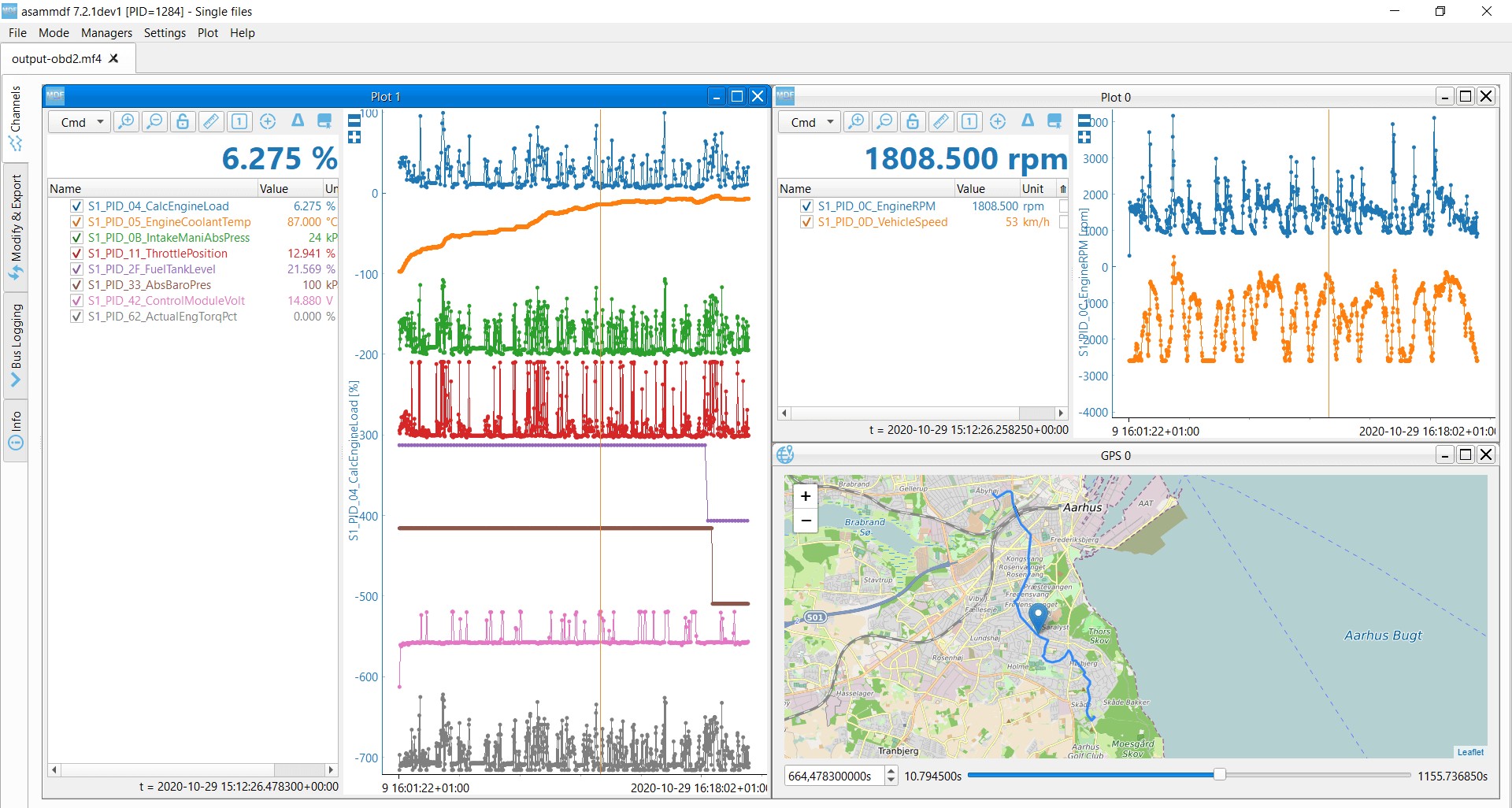 OBD2 data decoded visual plot asammdf CAN bus DBC file
11. What Are Examples of ISO OBD2 Multi-Frame Communication (ISO-TP)?
Multi-frame communication is essential for transmitting larger data packets like VINs and DTCs.
11.1 OBD2 Vehicle Identification Number (VIN)
To extract the Vehicle Identification Number from a vehicle using OBD2 requests, you use mode 0x09 and PID 0x02. The tester tool sends a Single Frame request with the PCI field (0x02), request service identifier (0x09) and PID (0x02). The vehicle responds with a First Frame containing the PCI, length (0x014 = 20 bytes), mode (0x49, i.e. 0x09 + 0x40) and PID (0x02).
11.2 OBD2 Multi-PID Request (6x)
External tools are allowed to request up to 6 mode 0x01 OBD2 PIDs in a single request frame. The ECU shall respond with data for supported PIDs (with unsupported PIDs left out of the response), if necessary across multiple frames as per ISO-TP.
11.3 OBD2 Diagnostic Trouble Codes (DTCs)
You can use OBD2 to request emissions-related Diagnostic Trouble Codes (DTCs) from using mode 0x03, i.e. ‘Show stored Diagnostic Trouble Codes’. The 2-byte DTC value is typically split into two parts, as per ISO 15031-5/ISO 15031-6. The first 2 bits define the ‘category’, while the remaining 14 bits define a 4-digit code (displayed in hexadecimal).
Visual representation of OBD2 DTC decoding, showing the structure of diagnostic trouble codes and their interpretation.
12. What Are the Use Case Examples for ISO OBD2 Data Logging?
OBD2 data logging has various applications, including reducing fuel costs, improving driving, and predictive maintenance.
12.1 Logging Data from Cars
OBD2 data from cars can e.g. be used to reduce fuel costs, improve driving, test prototype parts and insurance.
12.2 Real-Time Car Diagnostics
OBD2 interfaces can be used to stream human-readable OBD2 data in real-time, e.g. for diagnosing vehicle issues.
12.3 Predictive Maintenance
Cars and light trucks can be monitored via IoT OBD2 loggers in the cloud to predict and avoid breakdowns.
12.4 Vehicle Blackbox Logger
An OBD2 logger can serve as a ‘blackbox’ for vehicles or equipment, providing data for e.g. disputes or diagnostics.
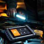
Illustration depicting OBD2 data logging in a car, showcasing its application in vehicle diagnostics and performance monitoring.
13. ISO OBD2 Protocol: Addressing Common Questions
Let’s address some frequently asked questions about the ISO OBD2 protocol to enhance your understanding.
13.1 What Exactly Is an ISO OBD2 Protocol?
The ISO OBD2 protocol is the standardized method vehicles use for on-board diagnostics, enabling the extraction of diagnostic trouble codes and real-time data via a standard connector.
13.2 Where Can I Locate the OBD2 Port in My Car?
The OBD2 port is typically located under the dashboard on the driver’s side. However, its exact location can vary by vehicle make and model.
13.3 Will Using an OBD2 Scanner Void My Car’s Warranty?
No, using an OBD2 scanner will not void your car’s warranty. The protocol is designed to allow vehicle owners and mechanics to diagnose issues without requiring proprietary tools.
13.4 What Kind of Information Can I Access Via OBD2?
You can access a wide range of information, including engine RPM, vehicle speed, coolant temperature, oxygen sensor readings, and diagnostic trouble codes.
13.5 How Can I Interpret the Data I Get from an OBD2 Scan?
Interpreting OBD2 data typically involves looking up diagnostic trouble codes in a code database or using OBD2 software that translates the raw data into readable information.
13.6 What Should I Do After I Identify a DTC?
After identifying a DTC, you should research the code to understand the potential causes. Depending on the severity, you may need to consult a professional mechanic.
13.7 Is It Possible to Clear DTCs Using an OBD2 Scanner?
Yes, most OBD2 scanners have the capability to clear DTCs. However, clearing a code does not fix the underlying issue, which will likely cause the code to reappear if not addressed.
13.8 Can I Use the Same OBD2 Scanner on Different Cars?
Yes, OBD2 scanners are designed to be compatible with all vehicles that support the OBD2 protocol, but it’s important to ensure compatibility with your specific vehicle to ensure accurate readings.
13.9 What Is the Difference Between OBD2 and OBD1?
OBD2 is a more advanced and standardized system compared to OBD1. OBD2 provides more detailed diagnostic information and is used in vehicles manufactured from 1996 onwards.
13.10 Are There Any Risks Associated With Using an OBD2 Scanner?
The primary risk is misinterpreting the data, which could lead to unnecessary repairs. Always ensure you have a clear understanding before making any changes to your vehicle.
Conclusion: Mastering the ISO OBD2 Protocol with OBD2-SCANNER.EDU.VN
The ISO OBD2 protocol is vital for modern vehicle diagnostics, and understanding its standards, functions, and future trends is essential for anyone involved in automotive repair or maintenance. By leveraging the information and services available at OBD2-SCANNER.EDU.VN, you can effectively diagnose and address vehicle issues, ensuring optimal performance and longevity.
Do you have an OBD2 data logging use case? For expert guidance on leveraging the ISO OBD2 protocol for your specific needs, contact us today!
Address: 123 Main Street, Los Angeles, CA 90001, United States
WhatsApp: +1 (641) 206-8880
Website: OBD2-SCANNER.EDU.VN
Our team at OBD2-SCANNER.EDU.VN is ready to assist you with all your OBD2-related inquiries, from understanding diagnostic codes to recommending the best tools and practices for your vehicle. Contact us now to unlock the full potential of your vehicle’s diagnostic capabilities and drive with confidence.