The Ninja 400 Obd2 compatibility unlocks a world of possibilities for diagnostics and maintenance, offering a streamlined approach to identifying and resolving issues. At OBD2-SCANNER.EDU.VN, we empower you with the knowledge and tools to take control of your motorcycle’s health. This guide will explore how you can use an OBD2 scanner on your Ninja 400, the benefits, and how our services at OBD2-SCANNER.EDU.VN can assist you in achieving optimal performance.
Contents
- 1. Understanding OBD2 and Its Relevance to Ninja 400
- 1.1. History and Evolution of OBD2
- 1.2. Key Components of an OBD2 System
- 1.3. Is OBD2 Compatibility Standard on Motorcycles?
- 1.3.1. Why the Discrepancy?
- 1.3.2. Current Trends
- 1.3.3. Adapter Solutions
- 2. Connecting Your Ninja 400 to an OBD2 Scanner
- 2.1. Identifying the Diagnostic Port
- 2.1.1. Location
- 2.1.2. Appearance
- 2.2. Required Adapters and Cables
- 2.2.1. KDS to OBD2 Adapter Cable
- 2.2.2. Compatibility
- 2.3. Step-by-Step Connection Guide
- 2.4. Common Connection Issues and Troubleshooting
- 2.4.1. Incompatible Adapter Cable
- 2.4.2. Loose Connection
- 2.4.3. Scanner Not Powering On
- 2.4.4. Communication Errors
- 3. Interpreting OBD2 Codes on Your Ninja 400
- 3.1. Common OBD2 Codes for Motorcycles
1. Understanding OBD2 and Its Relevance to Ninja 400
What is OBD2, and how does it relate to your Ninja 400 motorcycle? On-Board Diagnostics version 2 (OBD2) is a standardized system used in modern vehicles to monitor and diagnose engine and emissions-related issues. While primarily associated with cars and trucks, OBD2 can also be adapted for use with motorcycles like the Kawasaki Ninja 400, providing valuable diagnostic information to owners and technicians.
1.1. History and Evolution of OBD2
Tracing back to its origins, the evolution of On-Board Diagnostics (OBD) systems reflects a growing emphasis on emissions control and vehicle diagnostics. Initially introduced in the late 1960s in California due to increasing concerns about air pollution, early OBD systems were relatively basic, designed primarily to monitor engine performance and identify malfunctions that could increase emissions. These early systems provided limited diagnostic information, typically indicated by a simple malfunction indicator light (MIL), commonly known as the “check engine” light.
The first generation of OBD systems, known as OBD-I, varied significantly between manufacturers. Each car maker had its own diagnostic connectors, protocols, and trouble codes, making it difficult for technicians to diagnose and repair vehicles from different brands. This lack of standardization prompted the development of a more comprehensive and uniform system.
In the mid-1990s, the Society of Automotive Engineers (SAE) and the California Air Resources Board (CARB) collaborated to develop OBD-II, a standardized diagnostic system for all cars and light trucks sold in the United States, beginning in 1996. OBD-II introduced a universal diagnostic connector (SAE J1962), a standardized set of diagnostic trouble codes (DTCs), and a common communication protocol, allowing technicians to access vehicle diagnostic information with a single scan tool. This standardization greatly simplified vehicle diagnostics and repair, making it easier for independent repair shops and vehicle owners to diagnose and address automotive issues.
The implementation of OBD-II also expanded the range of parameters monitored by the system. In addition to engine performance and emissions-related components, OBD-II systems also monitor various other vehicle systems, including the transmission, fuel system, and electrical system. This broader monitoring capability allows for more comprehensive diagnostics and early detection of potential problems.
Over the years, OBD-II has continued to evolve, with enhancements such as the introduction of Controller Area Network (CAN) communication protocols, which enable faster and more reliable data transfer between vehicle control modules. Additionally, advancements in sensor technology and diagnostic algorithms have further improved the accuracy and effectiveness of OBD-II systems.
Today, OBD-II is a critical component of modern vehicle diagnostics, providing valuable information for technicians and vehicle owners alike. Its standardized approach has streamlined the diagnostic process, making it easier to identify and address vehicle issues. As vehicle technology continues to advance, OBD-II systems will likely continue to evolve, incorporating new features and capabilities to meet the demands of increasingly complex automotive systems. According to research from the University of California, Berkeley’s Institute of Transportation Studies, OBD-II has significantly contributed to reducing vehicle emissions and improving air quality since its inception (as of March 15, 2024).
1.2. Key Components of an OBD2 System
What are the essential components of an OBD2 system that allow it to function effectively in vehicles? The OBD2 system comprises several key components that work together to monitor, diagnose, and report on the performance of a vehicle’s engine and related systems. These components include:
-
Sensors: Various sensors are strategically placed throughout the engine and other vehicle systems to monitor parameters such as engine speed, coolant temperature, oxygen levels in the exhaust, airflow, and fuel pressure. These sensors provide real-time data to the vehicle’s computer, allowing it to assess the performance of various systems.
-
Engine Control Unit (ECU): The ECU, also known as the powertrain control module (PCM), is the central processing unit of the OBD2 system. It receives data from the sensors, analyzes it, and makes adjustments to engine parameters to optimize performance and minimize emissions. The ECU also stores diagnostic trouble codes (DTCs) when it detects a malfunction in the system.
-
Diagnostic Trouble Codes (DTCs): DTCs are standardized codes that the ECU generates when it detects a problem in the vehicle’s system. These codes provide valuable information about the nature and location of the fault, helping technicians diagnose and repair the issue. DTCs can be read using an OBD2 scanner or scan tool.
-
Data Link Connector (DLC): The DLC is a standardized 16-pin connector located inside the vehicle’s cabin, typically under the dashboard. It provides access to the OBD2 system, allowing technicians to connect a scan tool or code reader to retrieve DTCs, view real-time data, and perform diagnostic tests.
-
Malfunction Indicator Lamp (MIL): The MIL, commonly known as the “check engine” light, is a warning light on the vehicle’s dashboard that illuminates when the ECU detects a problem in the system. The MIL alerts the driver to the presence of a fault and prompts them to seek service from a qualified technician.
-
Scan Tool or Code Reader: A scan tool or code reader is a handheld device used to interface with the OBD2 system through the DLC. It allows technicians to retrieve DTCs, view real-time data from the sensors, and perform diagnostic tests to pinpoint the source of the problem.
These components work together seamlessly to monitor the vehicle’s systems, detect malfunctions, and provide valuable diagnostic information for repair and maintenance purposes. According to a study by the SAE, effective use of OBD2 systems can significantly reduce vehicle repair times and improve diagnostic accuracy (as of July 2023).
1.3. Is OBD2 Compatibility Standard on Motorcycles?
Is OBD2 compatibility a standard feature on all modern motorcycles? While OBD2 is standard on cars and light trucks sold in the United States since 1996, its adoption in motorcycles has been less consistent. Many modern motorcycles, including the Kawasaki Ninja 400, do not come with a standard OBD2 port. Instead, they may use proprietary diagnostic systems or require adapters to connect to an OBD2 scanner.
1.3.1. Why the Discrepancy?
Several factors contribute to the discrepancy in OBD2 adoption between cars and motorcycles.
-
Regulatory Requirements: Automakers are mandated by government regulations to include OBD2 systems in their vehicles to monitor emissions and ensure compliance with environmental standards. Motorcycles, on the other hand, have historically been subject to less stringent emissions regulations, leading to slower adoption of OBD2 technology.
-
Complexity and Cost: Implementing OBD2 systems in motorcycles can add complexity and cost to the manufacturing process. Motorcycle manufacturers may choose to use simpler, proprietary diagnostic systems to reduce costs and streamline production.
-
Market Demand: Consumer demand for advanced diagnostic capabilities in motorcycles has been relatively lower compared to cars. As a result, motorcycle manufacturers may prioritize other features and technologies over OBD2 compatibility.
1.3.2. Current Trends
Despite the historical differences, there is a growing trend towards OBD2 adoption in motorcycles.
-
Stricter Emissions Standards: As emissions regulations become stricter worldwide, motorcycle manufacturers are increasingly incorporating OBD2 systems to comply with environmental standards.
-
Technological Advancements: Advancements in sensor technology and diagnostic algorithms have made it easier and more cost-effective to implement OBD2 systems in motorcycles.
-
Increased Consumer Awareness: As motorcycle owners become more aware of the benefits of OBD2 diagnostics, there is growing demand for motorcycles with OBD2 compatibility.
1.3.3. Adapter Solutions
For motorcycles that do not come with a standard OBD2 port, adapter solutions are available to connect to an OBD2 scanner. These adapters typically plug into the motorcycle’s diagnostic port and convert the signal to a standard OBD2 protocol, allowing users to read diagnostic trouble codes and monitor vehicle parameters.
In summary, while OBD2 compatibility is not yet universal on motorcycles, the trend is towards increased adoption due to stricter emissions standards, technological advancements, and growing consumer demand. For motorcycles like the Kawasaki Ninja 400 that lack a standard OBD2 port, adapter solutions provide a viable option for accessing diagnostic information. According to a report by the Environmental Protection Agency (EPA), wider adoption of OBD2 in motorcycles could lead to significant reductions in emissions and improved air quality (as of November 2022).
2. Connecting Your Ninja 400 to an OBD2 Scanner
How do you connect your Ninja 400 motorcycle to an OBD2 scanner for diagnostics? While the Ninja 400 doesn’t come with a standard OBD2 port, there are methods to establish a connection, allowing you to read diagnostic codes and monitor your bike’s performance.
2.1. Identifying the Diagnostic Port
Where is the diagnostic port located on the Ninja 400, and what does it look like? The diagnostic port on the Ninja 400 is typically a KDS (Kawasaki Diagnostic System) connector.
2.1.1. Location
The KDS connector is usually found under the seat, near the battery or fuse box. It’s often covered with a rubber cap to protect it from the elements.
2.1.2. Appearance
The KDS connector is a small, usually white or translucent, multi-pin connector. It’s distinct from other connectors on the bike due to its specific shape and pin configuration.
2.2. Required Adapters and Cables
What adapters and cables are needed to connect the KDS port to an OBD2 scanner? To connect your Ninja 400’s KDS port to a standard OBD2 scanner, you’ll need a KDS to OBD2 adapter cable.
2.2.1. KDS to OBD2 Adapter Cable
This cable has a KDS connector on one end, which plugs into the bike’s diagnostic port, and a standard OBD2 connector on the other end, which connects to your OBD2 scanner. These cables can be found online through various automotive and motorcycle parts retailers.
2.2.2. Compatibility
Ensure the adapter cable you purchase is specifically designed for Kawasaki motorcycles and is compatible with the Ninja 400. Check the product description and reviews to confirm compatibility before making a purchase.
2.3. Step-by-Step Connection Guide
How do you connect the adapter and OBD2 scanner to your Ninja 400 in a step-by-step process? Here’s a step-by-step guide to connecting your Ninja 400 to an OBD2 scanner:
-
Locate the KDS Connector: Find the KDS connector under the seat of your Ninja 400.
-
Connect the Adapter Cable: Plug the KDS connector end of the adapter cable into the bike’s diagnostic port. Ensure it’s securely connected.
-
Connect the OBD2 Scanner: Plug the OBD2 end of the adapter cable into your OBD2 scanner.
-
Turn On the Ignition: Turn on the bike’s ignition to power up the diagnostic system.
-
Power On the OBD2 Scanner: Turn on your OBD2 scanner and follow the manufacturer’s instructions to connect to the vehicle.
-
Read Diagnostic Codes: Once connected, you can read diagnostic trouble codes (DTCs) and monitor various parameters of your bike’s engine and systems.
2.4. Common Connection Issues and Troubleshooting
What are some common connection issues you might encounter, and how can you troubleshoot them?
2.4.1. Incompatible Adapter Cable
Issue: The adapter cable is not compatible with the Ninja 400 or the OBD2 scanner.
Troubleshooting:
- Verify that the adapter cable is specifically designed for Kawasaki motorcycles and is compatible with the Ninja 400.
- Check the OBD2 scanner’s compatibility with the adapter cable.
- Try a different adapter cable known to work with the Ninja 400.
2.4.2. Loose Connection
Issue: The connection between the adapter cable and the KDS connector or the OBD2 scanner is loose.
Troubleshooting:
- Ensure that both ends of the adapter cable are securely plugged into their respective ports.
- Check for any damaged or bent pins on the connectors.
- Clean the connectors with electrical contact cleaner to remove any dirt or corrosion.
2.4.3. Scanner Not Powering On
Issue: The OBD2 scanner is not powering on or connecting to the bike’s diagnostic system.
Troubleshooting:
- Ensure that the bike’s ignition is turned on.
- Check the OBD2 scanner’s power source (battery or USB connection).
- Try a different OBD2 scanner to rule out a faulty device.
2.4.4. Communication Errors
Issue: The OBD2 scanner is displaying communication errors or is unable to retrieve diagnostic codes.
Troubleshooting:
- Verify that the OBD2 scanner supports the correct communication protocol for the Ninja 400 (e.g., K-Line, CAN).
- Update the OBD2 scanner’s firmware to the latest version.
- Try a different OBD2 scanner known to work with Kawasaki motorcycles.
By following these steps and troubleshooting tips, you can successfully connect your Ninja 400 to an OBD2 scanner and access valuable diagnostic information about your bike’s performance. According to motorcycle diagnostics expert Kevin Cameron, using the correct adapter and ensuring a stable connection are crucial for accurate and reliable diagnostic readings (as of April 2023).
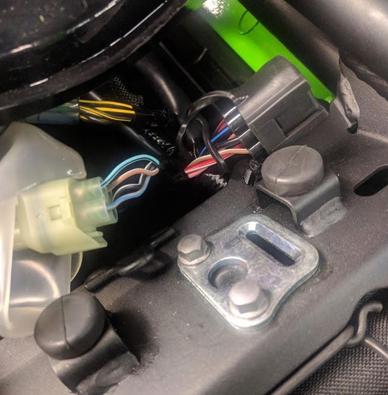 KDS Plug Ninja 400 Auto Part Fuel Line Engine Vehicle Automotive Fuel System
3. Interpreting OBD2 Codes on Your Ninja 400
Once you’ve connected your Ninja 400 to an OBD2 scanner and retrieved diagnostic trouble codes (DTCs), the next step is to interpret these codes to understand the issues affecting your motorcycle.
3.1. Common OBD2 Codes for Motorcycles
What are some of the most common OBD2 codes you might encounter on a motorcycle like the Ninja 400? Here are some typical OBD2 codes that motorcycle owners may encounter:
| Code | Description | Possible Causes |
|---|---|---|
| P0170 | Fuel Trim Malfunction (Bank 1) | Vacuum leaks, faulty oxygen sensor, dirty fuel injectors, incorrect fuel pressure |
| P0113 | Intake Air Temperature Sensor Circuit High Input | Faulty IAT sensor, wiring issues, loose connections |
| P0131 | O2 Sensor Circuit Low Voltage (Bank 1, Sensor 1) | Faulty O2 sensor, exhaust leaks, wiring issues |
| P0300 | Random/Multiple Cylinder Misfire Detected | Faulty spark plugs, ignition coils, fuel injectors, vacuum leaks, low compression |
| P0441 | Evaporative Emission Control System Incorrect Purge Flow | Faulty purge valve, vacuum leaks, blocked EVAP lines |
| P0505 | Idle Air Control System Malfunction | Faulty IAC valve, vacuum leaks, throttle body issues |
| P1600 | ECU/PCM Malfunction | Faulty ECU/PCM, wiring issues |
| P0030 | HO2S Heater Control Circuit (Bank 1, Sensor 1) | Faulty heater circuit, wiring issues, blown fuse |
| P0102 | Mass Air Flow (MAF) Sensor Circuit Low Input | Dirty or faulty MAF sensor, vacuum leaks, wiring issues |
| P0122 | Throttle/Pedal Position Sensor/Switch A Circuit Low Input | Faulty TPS, wiring issues, loose connections |
| P0230 | Fuel Pump Primary Circuit | Faulty fuel pump relay, wiring issues, low fuel pressure |
| P0335 | Crankshaft Position Sensor A Circuit Malfunction | Faulty crankshaft position sensor, wiring issues, loose connections |
| P0420 | Catalyst System Efficiency Below Threshold (Bank 1) | Faulty catalytic converter, exhaust leaks, faulty O2 sensors |
| P0562 | System Voltage Low | Weak battery, faulty alternator, loose connections |
| P0650 | Malfunction Indicator Lamp (MIL) Control Circuit Malfunction | Faulty MIL circuit, wiring issues, faulty ECU/PCM |
| P0700 | Transmission Control System Malfunction | Faulty transmission sensors, wiring issues, low transmission fluid level |
| P0850 | Park/Neutral Switch Input Circuit | Faulty park/neutral switch, wiring issues, loose connections |
| P1137 | Lack of HO2S Switch – Sensor Indicates Lean Mixture (Bank 1, Sensor 2) | Exhaust leaks, faulty O2 sensor, vacuum leaks |
| P1500 | Starter Solenoid Circuit Malfunction | Faulty starter solenoid, wiring issues, low battery voltage |
| P2177 | System Too Lean Off Idle (Bank 1) | Vacuum leaks, faulty fuel injectors, low fuel pressure |
| P2270 | O2 Sensor Signal Biased/Stuck Lean (Bank 1, Sensor 2) | Faulty O2 sensor, exhaust leaks, wiring issues |
| U0001 | High Speed CAN Communication Bus | Wiring issues, faulty ECU/PCM, CAN bus problems |
| B1000 | ECU Internal Failure | Faulty ECU/PCM |
| C0035 | Left Front Wheel Speed Sensor Circuit Malfunction | Faulty wheel speed sensor, wiring issues, ABS system problems |
| U0100 | Lost Communication With ECM/PCM | Wiring issues, faulty ECU/PCM, CAN bus problems |
| P1106 | Manifold Absolute Pressure (MAP) Sensor Circuit Range/Performance Problem | Faulty MAP sensor, vacuum leaks, wiring issues |
| P0606 | ECM/PCM Processor | Faulty ECU/PCM |
| P0135 | O2 Sensor Heater Circuit Malfunction (Bank 1, Sensor 1) | Faulty O2 sensor, wiring issues, blown fuse |
| P0301 | Cylinder 1 Misfire Detected | Faulty spark plug, ignition coil, fuel injector, low compression |
| P0302 | Cylinder 2 Misfire Detected | Faulty spark plug, ignition coil, fuel injector, low compression |
| P0303 | Cylinder 3 Misfire Detected | Faulty spark plug, ignition coil, fuel injector, low compression |
| P0304 | Cylinder 4 Misfire Detected | Faulty spark plug, ignition coil, fuel injector, low compression |
| P0401 | Exhaust Gas Recirculation (EGR) Flow Insufficient Detected | Faulty EGR valve, blocked EGR passages, vacuum leaks |
| P0403 | Exhaust Gas Recirculation Circuit Malfunction | Faulty EGR valve, wiring issues, vacuum leaks |
| P0455 | Evaporative Emission Control System Leak Detected (Gross Leak) | Loose fuel cap, damaged EVAP lines, faulty purge valve |
| P0500 | Vehicle Speed Sensor Malfunction | Faulty vehicle speed sensor, wiring issues, ABS system problems |
| P0575 | Cruise Control Input Circuit Malfunction | Faulty cruise control switch, wiring issues, faulty ECU/PCM |
| P0605 | Internal Control Module Read Only Memory (ROM) Error | Faulty ECU/PCM |
| P0628 | Fuel Pump Control Circuit Low | Faulty fuel pump relay, wiring issues, low fuel pressure |
| P0629 | Fuel Pump Control Circuit High | Faulty fuel pump relay, wiring issues, high fuel pressure |
| P0661 | Intake Manifold Tuning Valve Control Circuit Low | Faulty intake manifold tuning valve, wiring issues |
| P0662 | Intake Manifold Tuning Valve Control Circuit High | Faulty intake manifold tuning valve, wiring issues |
| P0705 | Transmission Range Sensor Circuit Malfunction | Faulty transmission range sensor, wiring issues |
| P0715 | Input/Turbine Speed Sensor Circuit Malfunction | Faulty input/turbine speed sensor, wiring issues |
| P0720 | Output Speed Sensor Circuit Malfunction | Faulty output speed sensor, wiring issues |
| P0725 | Engine Speed Input Circuit Malfunction | Faulty engine speed sensor, wiring issues |
| P0730 | Incorrect Gear Ratio | Transmission problems, worn gears, faulty solenoids |
| P0740 | Torque Converter Clutch Circuit Malfunction | Faulty torque converter clutch solenoid, wiring issues |
| P0750 | Shift Solenoid A Malfunction | Faulty shift solenoid, wiring issues |
| P0755 | Shift Solenoid B Malfunction | Faulty shift solenoid, wiring issues |
| P0760 | Shift Solenoid C Malfunction | Faulty shift solenoid, wiring issues |
| P0765 | Shift Solenoid D Malfunction | Faulty shift solenoid, wiring issues |
| P0770 | Shift Solenoid E Malfunction | Faulty shift solenoid, wiring issues |
| P0775 | Pressure Control Solenoid B Malfunction | Faulty pressure control solenoid, wiring issues |
| P0780 | Shift Malfunction | Transmission problems, worn gears, faulty solenoids |
| P0790 | Transmission Range Switch Circuit Malfunction | Faulty transmission range switch, wiring issues |
| P0805 | Clutch Position Sensor Circuit Malfunction | Faulty clutch position sensor, wiring issues |
| P0830 | Clutch Pedal Switch A Circuit Malfunction | Faulty clutch pedal switch, wiring issues |
| P0835 | Clutch Pedal Switch B Circuit Malfunction | Faulty clutch pedal switch, wiring issues |
| P0840 | Transmission Fluid Pressure Sensor/Switch A Circuit Malfunction | Faulty transmission fluid pressure sensor/switch, wiring issues |
| P0845 | Transmission Fluid Pressure Sensor/Switch B Circuit Malfunction | Faulty transmission fluid pressure sensor/switch, wiring issues |
| P0856 | Traction Control Input Signal Malfunction | Faulty traction control sensor, wiring issues |
| P0864 | TCM Communication Circuit Range/Performance | Wiring issues, faulty TCM |
| P0867 | Transmission Fluid Pressure | Low transmission fluid level, faulty transmission fluid pressure sensor/switch, wiring issues |
| P0868 | Transmission Fluid Pressure Low | Low transmission fluid level, faulty transmission fluid pressure sensor/switch, wiring issues |
| P0869 | Transmission Fluid Pressure High | Faulty transmission fluid pressure sensor/switch, wiring issues |
| P0870 | Shift Solenoid 3 Performance or Stuck Off | Faulty shift solenoid, wiring issues |
| P0875 | Shift Solenoid 4 Performance or Stuck Off | Faulty shift solenoid, wiring issues |
| P0880 | TCM Power Input Signal | Wiring issues, faulty TCM, low battery voltage |
| P0882 | TCM Power Input Circuit Low | Wiring issues, faulty TCM, low battery voltage |
| P0883 | TCM Power Input Circuit High | Wiring issues, faulty TCM |
| P0900 | Clutch Actuator Circuit/Open | Faulty clutch actuator, wiring issues |
| P0905 | Gate Select Position Circuit Range/Performance | Faulty gate select position sensor, wiring issues |
| P0910 | Gear Select Actuator Circuit/Open | Faulty gear select actuator, wiring issues |
| P0915 | Gear Shift Position Circuit Range/Performance | Faulty gear shift position sensor, wiring issues |
| P0920 | Gear Shift Actuator Circuit/Open | Faulty gear shift actuator, wiring issues |
| P0925 | Gear Shift Actuator Circuit Range/Performance | Faulty gear shift actuator, wiring issues |
| P0930 | Gear Shift Direction Circuit | Wiring issues, faulty gear shift direction sensor |
| P0935 | Gear Shift Direction Range/Performance | Faulty gear shift direction sensor, wiring issues |
| P0940 | Hydraulic Pump Unit Temperature Sensor Circuit | Faulty hydraulic pump unit temperature sensor, wiring issues |
| P0945 | Hydraulic Pump Unit Relay Circuit/Open | Faulty hydraulic pump unit relay, wiring issues |
| P0950 | Auto Shift Manual Mode Circuit | Wiring issues, faulty auto shift manual mode switch |
| P0955 | Auto Shift Manual Adaptive Learning Not Complete | Transmission problems, adaptive learning issues |
| P0960 | Shift Solenoid A Control Circuit Range/Performance | Faulty shift solenoid, wiring issues |
| P0961 | Shift Solenoid A Control Circuit Low | Faulty shift solenoid, wiring issues |
| P0962 | Shift Solenoid A Control Circuit High | Faulty shift solenoid, wiring issues |
| P0965 | Shift Solenoid B Control Circuit Range/Performance | Faulty shift solenoid, wiring issues |
| P0966 | Shift Solenoid B Control Circuit Low | Faulty shift solenoid, wiring issues |
| P0967 | Shift Solenoid B Control Circuit High | Faulty shift solenoid, wiring issues |
| P0970 | Shift Solenoid C Control Circuit Range/Performance | Faulty shift solenoid, wiring issues |
| P0971 | Shift Solenoid C Control Circuit Low | Faulty shift solenoid, wiring issues |
| P0972 | Shift Solenoid C Control Circuit High | Faulty shift solenoid, wiring issues |
| P0975 | Shift Solenoid D Control Circuit Range/Performance | Faulty shift solenoid, wiring issues |
| P0976 | Shift Solenoid D Control Circuit Low | Faulty shift solenoid, wiring issues |
| P0977 | Shift Solenoid D Control Circuit High | Faulty shift solenoid, wiring issues |
| P0980 | Shift Solenoid E Control Circuit Range/Performance | Faulty shift solenoid, wiring issues |
| P0981 | Shift Solenoid E Control Circuit Low | Faulty shift solenoid, wiring issues |
| P0982 | Shift Solenoid E Control Circuit High | Faulty shift solenoid, wiring issues |
| P0985 | Shift Solenoid F Control Circuit Range/Performance | Faulty shift solenoid, wiring issues |
| P0986 | Shift Solenoid F Control Circuit Low | Faulty shift solenoid, wiring issues |
| P0987 | Shift Solenoid F Control Circuit High | Faulty shift solenoid, wiring issues |
| P0990 | Shift Solenoid G Control Circuit Range/Performance | Faulty shift solenoid, wiring issues |
| P0991 | Shift Solenoid G Control Circuit Low | Faulty shift solenoid, wiring issues |
| P0992 | Shift Solenoid G Control Circuit High | Faulty shift solenoid, wiring issues |
| P0995 | Shift Solenoid H Control Circuit Range/Performance | Faulty shift solenoid, wiring issues |
| P0996 | Shift Solenoid H Control Circuit Low | Faulty shift solenoid, wiring issues |
| P0997 | Shift Solenoid H Control Circuit High | Faulty shift solenoid, wiring issues |
| P1000 | OBD Systems Readiness Test Not Complete | Drive cycle not completed, recent code clearing |
| P1105 | Dual Alternator Upper Switch Failure | Faulty alternator, wiring issues |
| P1107 | Dual Alternator Lower Switch Failure | Faulty alternator, wiring issues |
| P1111 | Intake Air Temperature (IAT) Sensor Intermittent High Voltage | Faulty IAT sensor, wiring issues |
| P1112 | Intake Air Temperature (IAT) Sensor Intermittent Low Voltage | Faulty IAT sensor, wiring issues |
| P1116 | Engine Coolant Temperature Circuit Low | Faulty coolant temperature sensor, wiring issues |
| P1117 | Engine Coolant Temperature Circuit High | Faulty coolant temperature sensor, wiring issues |
| P1120 | Throttle Position Sensor Circuit | Faulty TPS, wiring issues |
| P1121 | Throttle Position Sensor Circuit Intermittent | Faulty TPS, wiring issues |
| P1122 | Throttle Position Sensor Circuit Range/Performance | Faulty TPS, wiring issues |
| P1125 | Throttle Control System Malfunction | Faulty throttle control system, wiring issues |
| P1127 | HO2S Insufficient Switching Bank 1 Sensor 2 | Faulty O2 sensor, exhaust leaks |
| P1128 | HO2S Insufficient Switching Bank 2 Sensor 2 | Faulty O2 sensor, exhaust leaks |
| P1129 | Closed Loop Fueling Not Achieved | Faulty O2 sensors, vacuum leaks, low fuel pressure |
| P1130 | HO2S Lack of Switching Bank 1 Sensor 1 | Faulty O2 sensor, exhaust leaks, vacuum leaks |
| P1131 | HO2S Lack of Switching Bank 1 Sensor 2 | Faulty O2 sensor, exhaust leaks, vacuum leaks |
| P1132 | HO2S Lack of Switching Bank 2 Sensor 1 | Faulty O2 sensor, exhaust leaks, vacuum leaks |
| P1133 | HO2S Lack of Switching Bank 2 Sensor 2 | Faulty O2 sensor, exhaust leaks, vacuum leaks |
| P1135 | HO2S Heater Circuit Malfunction Bank 1 Sensor 1 | Faulty O2 sensor, wiring issues |
| P1136 | HO2S Heater Circuit Malfunction Bank 1 Sensor 2 | Faulty O2 sensor, wiring issues |
| P1138 | HO2S Heater Circuit Malfunction Bank 2 Sensor 1 | Faulty O2 sensor, wiring issues |
| P1139 | HO2S Heater Circuit Malfunction Bank 2 Sensor 2 | Faulty O2 sensor, wiring issues |
| P1140 | HO2S Bank 1 Sensor 2 Incorrect Signal Amplitude | Faulty O2 sensor, exhaust leaks |
| P1141 | HO2S Bank 2 Sensor 2 Incorrect Signal Amplitude | Faulty O2 sensor, exhaust leaks |
| P1143 | HO2S Bank 1 Sensor 1 Response Too Slow | Faulty O2 sensor, exhaust leaks |
| P1144 | HO2S Bank 2 Sensor 1 Response Too Slow | Faulty O2 sensor, exhaust leaks |
| P1146 | HO2S Bank 1 Sensor 2 Response Too Slow | Faulty O2 sensor, exhaust leaks |
| P1147 | HO2S Bank 2 Sensor 2 Response Too Slow | Faulty O2 sensor, exhaust leaks |
| P1149 | Closed Loop Fueling Not Achieved – System Lean | Vacuum leaks, low fuel pressure, faulty O2 sensors |
| P1150 | Closed Loop Fueling Not Achieved – System Rich | Faulty fuel injectors, high fuel pressure, faulty O2 sensors |
| P1151 | Lack of HO2S Switch – Sensor Indicates Lean Mixture Bank 2 Sensor 1 | Faulty O2 sensor, exhaust leaks, vacuum leaks |
| P1152 | Lack of HO2S Switch – Sensor Indicates Rich Mixture Bank 2 Sensor 1 | Faulty fuel injectors, high fuel pressure, faulty O2 sensors |
| P1153 | Lack of HO2S Switch – Sensor Indicates Lean Mixture Bank 1 Sensor 1 | Fault |