The Obd2 Ecu Pinout refers to the specific arrangement of pins on the Engine Control Unit (ECU) connector of vehicles compliant with the OBD2 standard, and it’s crucial for diagnosing, reprogramming, and modifying the ECU. Understanding the OBD2 ECU pinout empowers technicians and enthusiasts to accurately interface with the vehicle’s computer system, and OBD2-SCANNER.EDU.VN is here to help you navigate this complex landscape, ensuring you have the correct information for your automotive needs. By providing precise pinout data and expert guidance, we enhance your ability to troubleshoot issues, optimize performance, and maintain your vehicle effectively, including understanding diagnostic trouble codes and the CAN bus system.
Contents
- 1. Understanding the Basics of OBD2 and ECU
- 1.1 What is OBD2?
- 1.2 What is an ECU?
- 1.3 Why is the OBD2 ECU Pinout Important?
- 2. Identifying Your Vehicle’s OBD2 ECU Pinout
- 2.1 Locating the ECU
- 2.2 Identifying the ECU Connector
- 2.3 Using a Vehicle-Specific Service Manual
- 2.4 Online Databases and Forums
- 2.5 Common OBD2 ECU Pinout Variations
- 3. Essential Tools for Working with OBD2 ECU Pinouts
- 3.1 Multimeter
- 3.2 Oscilloscope
- 3.3 OBD2 Scanner
- 3.4 Breakout Box
- 3.5 Wiring Diagrams
- 4. Understanding Common OBD2 ECU Pin Functions
- 4.1 Power Supply Pins
- 4.2 Ground Pins
- 4.3 Sensor Input Pins
- 4.4 Actuator Output Pins
- 4.5 Communication Pins
- 5. OBD2 ECU Pinout Diagrams for Popular Vehicles
- 5.1 Honda Civic (1996-2000)
- OBD2A (1996-1998)
- OBD2B (1999-2000)
- 5.2 Ford F-150 (2004-2008)
- 5.3 BMW 3 Series (E46 – 1998-2006)
- 6. Common Issues and Troubleshooting Tips
- 6.1 Incorrect Pin Identification
- 6.2 Pin Corrosion or Damage
- 6.3 Short Circuits
- 6.4 Open Circuits
- 6.5 Communication Errors
- 7. Advanced Techniques for ECU Diagnosis and Modification
- 7.1 ECU Flashing and Reprogramming
- 7.2 ECU Tuning and Mapping
- 7.3 Piggyback ECUs
- 8. Safety Precautions When Working with OBD2 ECU Pinouts
- 8.1 Disconnect the Battery
- 8.2 Use Proper Tools
- 8.3 Avoid Static Electricity
- 8.4 Double-Check Connections
- 8.5 Refer to Service Manuals
- 9. The Future of OBD2 and ECU Technology
- 9.1 Advancements in OBD3
- 9.2 Increasing Complexity of ECUs
- 9.3 The Role of Artificial Intelligence (AI)
- 10. Frequently Asked Questions (FAQs) About OBD2 ECU Pinouts
1. Understanding the Basics of OBD2 and ECU
1.1 What is OBD2?
OBD2, or On-Board Diagnostics II, is a standardized system used in most vehicles since 1996 to monitor and control engine performance, emissions, and other critical systems. According to the Environmental Protection Agency (EPA), OBD2 was implemented to ensure vehicles meet stringent emission standards and provide technicians with a universal method for diagnosing problems.
1.2 What is an ECU?
The Engine Control Unit (ECU) is the central computer in a vehicle that controls various functions, including fuel injection, ignition timing, and emission controls. Research from Bosch indicates that modern ECUs can process millions of instructions per second, managing a vast array of sensors and actuators to optimize vehicle performance.
1.3 Why is the OBD2 ECU Pinout Important?
The OBD2 ECU pinout is a detailed map of each pin on the ECU connector, indicating its specific function, such as sensor inputs, actuator outputs, power supply, and communication lines. According to a study by the Society of Automotive Engineers (SAE), knowing the correct pinout is essential for:
- Accurate Diagnostics: Pinouts help technicians connect diagnostic tools to the correct pins to read data and identify issues.
- Reprogramming: Correct pin connections are needed for flashing or remapping the ECU to optimize performance or address software glitches.
- Custom Modifications: Enthusiasts use pinouts to interface with the ECU for custom tuning, adding features, or modifying existing functions.
2. Identifying Your Vehicle’s OBD2 ECU Pinout
2.1 Locating the ECU
The ECU’s location varies depending on the vehicle’s make and model. Common locations include:
- Under the Dashboard: Often found on the passenger or driver’s side.
- Under the Seats: Some vehicles have the ECU mounted under the front seats.
- In the Engine Bay: Typically near the firewall or mounted on the fender.
Refer to your vehicle’s service manual for the exact location.
2.2 Identifying the ECU Connector
Once you’ve located the ECU, identify the connector you need. Modern ECUs often have multiple connectors, each serving different functions. The connector of interest will typically have a large number of pins and may be labeled or color-coded.
2.3 Using a Vehicle-Specific Service Manual
The most reliable way to find your vehicle’s OBD2 ECU pinout is by consulting the vehicle-specific service manual. These manuals provide detailed diagrams and descriptions of each pin’s function.
2.4 Online Databases and Forums
Several online databases and automotive forums may contain pinout information for various vehicles. Websites like AllData and Mitchell OnDemand are subscription-based services that offer comprehensive repair information, including ECU pinouts. Automotive forums can also be a valuable resource, but verify the information against other sources to ensure accuracy.
2.5 Common OBD2 ECU Pinout Variations
While OBD2 is a standardized system, the ECU pinouts can vary significantly between manufacturers and models. For instance, Honda ECUs will have different pinouts compared to Ford or BMW ECUs. Even within the same manufacturer, pinouts can change between model years.
3. Essential Tools for Working with OBD2 ECU Pinouts
3.1 Multimeter
A multimeter is essential for testing continuity, voltage, and resistance on the ECU pins. This helps verify that the pins are functioning correctly and that there are no shorts or open circuits.
3.2 Oscilloscope
An oscilloscope allows you to visualize electrical signals, which is crucial for diagnosing communication issues and sensor outputs. It can display waveforms, frequency, and amplitude, providing a detailed view of the signals passing through the ECU pins.
3.3 OBD2 Scanner
An OBD2 scanner is used to read diagnostic trouble codes (DTCs) and monitor live data from the ECU. This tool helps identify potential issues and verify that the ECU is communicating correctly with other vehicle systems.
3.4 Breakout Box
A breakout box provides a convenient way to access the ECU pins without damaging the connector. It allows you to connect test equipment and monitor signals without directly probing the ECU connector.
3.5 Wiring Diagrams
Wiring diagrams are essential for understanding the electrical connections within the vehicle. They show how the ECU is connected to various sensors, actuators, and other components.
4. Understanding Common OBD2 ECU Pin Functions
4.1 Power Supply Pins
These pins provide the ECU with the necessary voltage to operate. There are typically two types of power supply pins:
- Battery Voltage (B+): Provides constant power from the battery.
- Ignition Voltage: Provides power when the ignition switch is turned on.
4.2 Ground Pins
Ground pins provide a return path for electrical current, ensuring that the ECU has a stable reference point. There are usually multiple ground pins to ensure proper grounding.
4.3 Sensor Input Pins
These pins receive signals from various sensors throughout the vehicle, such as:
- Manifold Absolute Pressure (MAP) Sensor: Measures the pressure in the intake manifold.
- Throttle Position Sensor (TPS): Measures the position of the throttle plate.
- Engine Coolant Temperature (ECT) Sensor: Measures the temperature of the engine coolant.
- Oxygen (O2) Sensors: Measure the oxygen content in the exhaust gases.
4.4 Actuator Output Pins
These pins send signals to control various actuators, such as:
- Fuel Injectors: Control the amount of fuel injected into the engine.
- Ignition Coils: Control the timing and intensity of the spark.
- Idle Air Control (IAC) Valve: Controls the amount of air bypassing the throttle plate.
- EGR Valve: Controls the amount of exhaust gas recirculated into the intake manifold.
4.5 Communication Pins
These pins are used for communication with other vehicle systems and diagnostic tools. Common communication protocols include:
- CAN (Controller Area Network): A high-speed communication protocol used for transmitting data between ECUs.
- K-Line: A single-wire communication protocol used for diagnostics.
- L-Line: Another single-wire communication protocol used for diagnostics.
5. OBD2 ECU Pinout Diagrams for Popular Vehicles
Note: The following diagrams are for illustrative purposes only. Always consult the vehicle-specific service manual for accurate pinout information.
5.1 Honda Civic (1996-2000)
OBD2A (1996-1998)
Connector A
- Pin 1: Injector 4
- Pin 2: Injector 3
- Pin 3: Injector 2
- Pin 4: Injector 1
- Pin 5: Secondary O2 Sensor Heater Control
- Pin 6: Primary O2 Sensor Heater Control
- Pin 7: EGR Control Solenoid Valve
- Pin 8: VTEC Solenoid
- Pin 9: Logic Ground
- Pin 10: Power Ground
- Pin 11: Power Source
- Pin 12: Idle Air Control Valve
- Pin 15: Evap Purge Control Solenoid Valve
- Pin 16: Fuel Pump Relay
- Pin 17: A/C Controller
- Pin 18: Malfunction Indicator Light
- Pin 19: Alternator Control
- Pin 20: Ignition Control Module
- Pin 22: Logic Ground
- Pin 23: Power Ground
- Pin 24: Power Source
- Pin 27: Radiator Fan Control
- Pin 28: Evap Bypass Solenoid Valve
- Pin 29: Evap Control Canister Vent Shut Valve
- Pin 30: Brake Lock
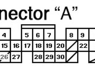 OBD2A Connector A Pinouts Chart
Connector C
- Pin 1: CKF Sensor P-side
- Pin 2: CKF Sensor P-side
- Pin 3: TDC Sensor P-side
- Pin 4: CYP Sensor P-side
- Pin 5: A/C Switch Signal
- Pin 6: Starter Signal Switch
- Pin 7: Service Check Signal
- Pin 8: K-Line
- Pin 9: A/T TCM related
- Pin 10: Voltage Backup
- Pin 11: CKF Ground
- Pin 12: CKP Ground
- Pin 13: TDC Ground
- Pin 14: CYP Ground
- Pin 15: VTEC Pressure Switch
- Pin 16: Power Steering Switch Signal
- Pin 17: Alternator FR Signal
- Pin 18: Vehicle Speed Sensor
- Pin 19: Detects TCM Signal
- Pin 21: Barometric Sensor Output
- Pin 23: HO2S Pump Cell
- Pin 24: HO2S Common
- Pin 25: VS Cell Voltage
- Pin 27: A/T TCM Related
- Pin 28: A/T TCM Related
- Pin 29: A/T Park + Neutral or Clutch Switch
- Pin 30: A/T Related to TCM
Connector D
- Pin 1: Throttle Position Sensor
- Pin 2: Engine Coolant Temp Sensor
- Pin 3: Manifold Absolute Pressure Sensor
- Pin 4: Sensor Voltage for MAP
- Pin 5: Brake Switch
- Pin 6: Knock Sensor
- Pin 7: Primary Heated O2 Sensor 1
- Pin 8: Intake Air Temp
- Pin 9: EGR Valve Lift Sensor
- Pin 10: Sensor Voltage
- Pin 11: Sensor Ground
- Pin 12: Sensor Ground
- Pin 13: Secondary Heated O2 Sensor Ground
- Pin 14: Secondary Heated O2 Sensor 2
- Pin 15: Fuel Tank Pressure Sensor
- Pin 16: Electric Load Detector
OBD2B (1999-2000)
Connector A
- Pin 3: EVAP Bypass Solenoid Valve
- Pin 4: EVAP Control Canister Vent Shut Valve
- Pin 5: Cruise Control Signal
- Pin 6: EVAP Purge Control Solenoid Valve
- Pin 7: A/T Gear Position Switch
- Pin 8: Second O2 Sensor Heater Control
- Pin 9: A/T Gear Position Switch
- Pin 10: Service Check Signal
- Pin 14: A/T D4 Indicator
- Pin 15: Fuel Pump Relay (Integra)
- Pin 16: Fuel Pump Relay (Civic)
- Pin 17: A/C Clutch Relay
- Pin 18: Malfunction Indicator Light
- Pin 19: Engine Speed Pulse
- Pin 20: Radiator Fan Control
- Pin 21: K-Line
- Pin 22: A/T Gear Position Switch
- Pin 23: Secondary Heated O2 Sensor 2
- Pin 24: Started Signal Switch
- Pin 26: Power Steering Power Switch Signal
- Pin 27: A/C Switch Signal
- Pin 28: A/T Brake Related
- Pin 29: Fuel Tank Pressure
- Pin 30: Electrical Load Detector
Connector B
- Pin 1: Power Source
- Pin 2: Power Ground
- Pin 3: Injector 2
- Pin 4: Injector 3
- Pin 5: Injector 4
- Pin 6: IACV Position Side
- Pin 7: EGR Control Solenoid Valve
- Pin 8: HLC LSM
- Pin 9: Power Source
- Pin 10: Power Ground
- Pin 11: Injector 1
- Pin 12: VTEC Solenoid
- Pin 13: Ignition Control Module
- Pin 15: IACV Negative Side
- Pin 16: Intake Air Bypass Control Solenoid Valve
- Pin 17: LS+HLC LSM
- Pin 18: SC LSM
- Pin 20: Logic Ground
- Pin 21: Voltage Backup
- Pin 22: Logic Ground
- Pin 23: Idle Air Control Valve
- Pin 25: SC LSP
Connector C
- Pin 1: Primary O2 Sensor Heater Control
- Pin 2: Alternator Control
- Pin 3: Knock Sensor
- Pin 5: Alternator FR Signal
- Pin 6: EGR Valve Lift Sensor
- Pin 7: Sensor Ground, Ground for MAP
- Pin 8: CKP Sensor P-side
- Pin 9: CKP Sensor M-side
- Pin 10: VTEC Pressure Switch
- Pin 16: Primary Heated O2 Sensor 1
- Pin 17: Manifold Absolute Pressure Sensor
- Pin 18: Sensor Ground
- Pin 19: Sensor Voltage for MAP
- Pin 20: TDC Sensor P-side
- Pin 21: TDC Sensor M-side
- Pin 22: CKF Sensor P-side
- Pin 23: Vehicle Speed Sensor
- Pin 25: Intake Air Temp
- Pin 26: Engine Coolant Temp Sensor
- Pin 27: Throttle Position Sensor
- Pin 28: Sensor Voltage
- Pin 29: CYP Sensor P-side
- Pin 30: CYP Sensor M-side
- Pin 31: CKF Sensor M-side
5.2 Ford F-150 (2004-2008)
Note: Pinouts can vary based on engine type and specific model year. Consult the service manual for your exact vehicle.
Connector C175b (PCM)
- Pin 1: Powertrain Control Module (PCM) Power Relay Output
- Pin 2: Keep Alive Power (PCM)
- Pin 3: Signal Return
- Pin 4: Vehicle Speed Sensor (VSS) Signal
- Pin 5: Transmission Control Switch Signal
- Pin 6: CAN High (+)
- Pin 7: CAN Low (-)
- Pin 8: Output Shaft Speed (OSS) Sensor Signal
- Pin 9: Transmission Fluid Temperature (TFT) Sensor Signal
- Pin 10: Turbine Shaft Speed (TSS) Sensor Signal
Connector C175e (PCM)
- Pin 1: Injector Control Signal – Cylinder 1
- Pin 2: Injector Control Signal – Cylinder 2
- Pin 3: Injector Control Signal – Cylinder 3
- Pin 4: Injector Control Signal – Cylinder 4
- Pin 5: Injector Control Signal – Cylinder 5
- Pin 6: Injector Control Signal – Cylinder 6
- Pin 7: Injector Control Signal – Cylinder 7
- Pin 8: Injector Control Signal – Cylinder 8
- Pin 9: Ignition Coil Control – Cylinder 1
- Pin 10: Ignition Coil Control – Cylinder 2
- Pin 11: Ignition Coil Control – Cylinder 3
- Pin 12: Ignition Coil Control – Cylinder 4
- Pin 13: Ignition Coil Control – Cylinder 5
- Pin 14: Ignition Coil Control – Cylinder 6
- Pin 15: Ignition Coil Control – Cylinder 7
- Pin 16: Ignition Coil Control – Cylinder 8
5.3 BMW 3 Series (E46 – 1998-2006)
Note: Pinouts can vary based on engine type and specific model year. Consult the service manual for your exact vehicle.
Digital Motor Electronics (DME) Control Module
- Pin 1: Terminal 87 Voltage Supply
- Pin 2: DME Main Relay Activation
- Pin 3: Signal, Air Conditioning Compressor
- Pin 4: Signal, Coolant Temperature
- Pin 5: Signal, Intake Air Temperature
- Pin 6: Signal, Throttle Position Sensor
- Pin 7: Signal, Mass Air Flow Sensor
- Pin 8: Signal, Oxygen Sensor Before Catalytic Converter
- Pin 9: Signal, Oxygen Sensor After Catalytic Converter
- Pin 10: Signal, Crankshaft Position Sensor
- Pin 11: Signal, Camshaft Position Sensor
- Pin 12: Signal, Knock Sensor 1
- Pin 13: Signal, Knock Sensor 2
- Pin 14: Activation, Fuel Injector Cylinder 1
- Pin 15: Activation, Fuel Injector Cylinder 2
- Pin 16: Activation, Fuel Injector Cylinder 3
- Pin 17: Activation, Fuel Injector Cylinder 4
- Pin 18: Activation, Ignition Coil Cylinder 1
- Pin 19: Activation, Ignition Coil Cylinder 2
- Pin 20: Activation, Ignition Coil Cylinder 3
- Pin 21: Activation, Ignition Coil Cylinder 4
6. Common Issues and Troubleshooting Tips
6.1 Incorrect Pin Identification
Issue: Using the wrong pinout diagram can lead to incorrect connections and potential damage to the ECU or other components.
Troubleshooting Tip: Always double-check the pinout information against the vehicle-specific service manual and verify with multiple sources if possible.
6.2 Pin Corrosion or Damage
Issue: Corrosion or physical damage to the ECU pins can cause poor connections and intermittent issues.
Troubleshooting Tip: Inspect the pins for corrosion or damage. Clean corroded pins with a contact cleaner or replace damaged pins or connectors.
6.3 Short Circuits
Issue: Short circuits can occur if wires are damaged or improperly connected, leading to ECU malfunctions or blown fuses.
Troubleshooting Tip: Use a multimeter to check for shorts between pins or between pins and ground. Repair or replace damaged wires and ensure proper insulation.
6.4 Open Circuits
Issue: Open circuits can occur if wires are broken or connectors are loose, preventing signals from reaching the ECU.
Troubleshooting Tip: Use a multimeter to check for continuity between the ECU and the connected components. Repair or replace broken wires and ensure connectors are securely connected.
6.5 Communication Errors
Issue: Communication errors can occur if there are issues with the CAN bus or other communication protocols.
Troubleshooting Tip: Use an oscilloscope to monitor the CAN bus signals and check for proper voltage levels and waveforms. Verify that the communication pins are correctly connected and that there are no shorts or open circuits.
7. Advanced Techniques for ECU Diagnosis and Modification
7.1 ECU Flashing and Reprogramming
ECU flashing involves overwriting the existing software on the ECU with a new version. This can be done to:
- Improve Performance: Optimize fuel and ignition settings for increased power and torque.
- Fix Software Glitches: Address bugs or issues in the original software.
- Adapt to Modifications: Adjust the ECU settings to accommodate aftermarket parts, such as turbochargers or larger injectors.
Tools Required:
- ECU Flashing Software: Programs like WinOLS, EcuFlash, and others.
- OBD2 Interface Cable: A cable that connects your computer to the vehicle’s OBD2 port.
- Stable Power Supply: To ensure the ECU doesn’t lose power during the flashing process.
Procedure:
- Connect the OBD2 interface cable to the vehicle’s OBD2 port and your computer.
- Launch the ECU flashing software and select the correct vehicle and ECU type.
- Load the new software file (calibration) into the flashing software.
- Follow the on-screen instructions to flash the ECU.
- Verify that the flashing process was successful and that the vehicle starts and runs correctly.
7.2 ECU Tuning and Mapping
ECU tuning involves adjusting specific parameters in the ECU software to optimize performance. This can include:
- Fuel Mapping: Adjusting the amount of fuel injected at different engine speeds and loads.
- Ignition Timing: Adjusting the timing of the spark to maximize power and efficiency.
- Boost Control: Adjusting the boost pressure of a turbocharger.
Tools Required:
- ECU Tuning Software: Programs like TunerStudio, AEM EMS, and others.
- Wideband O2 Sensor: To monitor the air-fuel ratio in real-time.
- Data Logging Software: To record engine parameters during tuning.
Procedure:
- Connect the wideband O2 sensor to the vehicle’s exhaust system and connect the data logging software to the ECU.
- Start the engine and monitor the air-fuel ratio and other engine parameters.
- Adjust the fuel and ignition maps in the ECU tuning software to achieve the desired performance.
- Repeat the process, making small adjustments and monitoring the results until the desired performance is achieved.
7.3 Piggyback ECUs
Piggyback ECUs are aftermarket devices that intercept and modify the signals between the ECU and the engine. They can be used to:
- Adjust Fuel and Ignition: Modify the fuel and ignition settings without flashing the ECU.
- Add Features: Add features like launch control, boost control, and nitrous control.
Installation:
- Identify the ECU pins that need to be connected to the piggyback ECU.
- Connect the piggyback ECU to the ECU pins, following the instructions provided by the manufacturer.
- Configure the piggyback ECU using the provided software.
8. Safety Precautions When Working with OBD2 ECU Pinouts
8.1 Disconnect the Battery
Before working on the ECU, disconnect the negative terminal of the battery to prevent electrical shorts or damage.
8.2 Use Proper Tools
Use high-quality tools that are specifically designed for automotive electrical work. This includes insulated screwdrivers, pliers, and wire strippers.
8.3 Avoid Static Electricity
Static electricity can damage sensitive electronic components in the ECU. Ground yourself by touching a metal part of the vehicle before touching the ECU or its connectors.
8.4 Double-Check Connections
Before applying power to the ECU, double-check all connections to ensure they are correct and secure.
8.5 Refer to Service Manuals
Always refer to the vehicle-specific service manual for accurate information and procedures.
9. The Future of OBD2 and ECU Technology
9.1 Advancements in OBD3
OBD3 is the next generation of on-board diagnostics, which will include more comprehensive monitoring and reporting capabilities. According to the EPA, OBD3 will likely include:
- Real-Time Emissions Monitoring: Continuously monitoring emissions and reporting violations to regulatory agencies.
- Remote Diagnostics: Allowing technicians to remotely diagnose and repair vehicles.
- Enhanced Security: Protecting the ECU from unauthorized access and tampering.
9.2 Increasing Complexity of ECUs
Modern ECUs are becoming increasingly complex, with more sensors, actuators, and communication protocols. This complexity requires technicians to have a deeper understanding of ECU pinouts and advanced diagnostic techniques.
9.3 The Role of Artificial Intelligence (AI)
AI is beginning to play a role in automotive diagnostics, with AI-powered tools that can analyze data from the ECU and provide technicians with insights and recommendations. As AI technology advances, it will likely become an even more valuable tool for diagnosing and repairing vehicles.
10. Frequently Asked Questions (FAQs) About OBD2 ECU Pinouts
10.1 What is an OBD2 ECU pinout?
An OBD2 ECU pinout is a detailed diagram showing the function of each pin on the Engine Control Unit (ECU) connector in OBD2-compliant vehicles.
10.2 Why is the OBD2 ECU pinout important?
It is crucial for accurate diagnostics, reprogramming, custom modifications, and ensuring correct connections when interfacing with the vehicle’s computer system.
10.3 Where can I find the OBD2 ECU pinout for my vehicle?
Consult your vehicle’s service manual, online databases like AllData or Mitchell OnDemand, or automotive forums, but always verify the information’s accuracy.
10.4 What tools do I need to work with OBD2 ECU pinouts?
Essential tools include a multimeter, oscilloscope, OBD2 scanner, breakout box, and wiring diagrams.
10.5 What are the common functions of OBD2 ECU pins?
Common functions include power supply, ground, sensor inputs, actuator outputs, and communication pins.
10.6 What are some common issues when working with OBD2 ECU pinouts?
Common issues include incorrect pin identification, pin corrosion or damage, short circuits, open circuits, and communication errors.
10.7 How can I troubleshoot communication errors with the ECU?
Use an oscilloscope to monitor the CAN bus signals and check for proper voltage levels and waveforms, ensuring correct connections and no shorts or open circuits.
10.8 What safety precautions should I take when working with OBD2 ECU pinouts?
Always disconnect the battery, use proper tools, avoid static electricity, double-check connections, and refer to service manuals.
10.9 What is ECU flashing?
ECU flashing involves overwriting the existing software on the ECU with a new version to improve performance, fix software glitches, or adapt to modifications.
10.10 What is ECU tuning?
ECU tuning involves adjusting specific parameters in the ECU software, like fuel mapping and ignition timing, to optimize performance.
Navigating the intricacies of OBD2 ECU pinouts can be challenging, but with the right knowledge and tools, you can effectively diagnose, repair, and modify your vehicle’s computer system. At OBD2-SCANNER.EDU.VN, we’re dedicated to providing you with the most accurate and up-to-date information to empower your automotive endeavors.
Do you have questions about your specific vehicle’s OBD2 ECU pinout or need assistance with diagnostics and repairs? Contact us today for expert guidance and support. Reach out at 123 Main Street, Los Angeles, CA 90001, United States, via WhatsApp at +1 (641) 206-8880, or visit our website at OBD2-SCANNER.EDU.VN for more information. Let OBD2-SCANNER.EDU.VN be your trusted partner in automotive diagnostics and repair.