An Obd2 Schematic is a detailed diagram illustrating the connections and components within an On-Board Diagnostics II (OBD2) system, and understanding this schematic is crucial for effective vehicle diagnostics and repair; at OBD2-SCANNER.EDU.VN, we simplify this complexity, offering clear guidance and resources. Grasping the essentials of an OBD II diagnostic chart, wiring diagrams, and diagnostic link connector can significantly enhance your ability to troubleshoot car issues.
Contents
- 1. What Is an OBD2 Schematic?
- 1.1. Definition of OBD2 Schematic
- 1.2. Purpose of OBD2 Schematic
- 1.3. Key Components Illustrated in an OBD2 Schematic
- 2. Understanding the Basics of OBD2 System
- 2.1. Overview of OBD2 System
- 2.2. Essential Components of OBD2 System
- 2.3. How Data Flows Within the OBD2 System
- 3. How to Read an OBD2 Schematic
- 3.1. Common Symbols and Abbreviations
- 3.2. Tracing Electrical Circuits
- 3.3. Interpreting Wiring Diagrams
- 4. Essential Tools for Working with OBD2 Schematics
- 4.1. Multimeters
- 4.2. Scan Tools
- 4.3. Wiring Test Kits
- 5. Common OBD2 Diagnostic Scenarios
- 5.1. Identifying Open Circuits
- 5.2. Diagnosing Short Circuits
- 5.3. Troubleshooting Sensor Failures
- 6. Step-by-Step Guide to Diagnosing a Fault Using OBD2 Schematic
- 6.1. Step 1: Retrieve Diagnostic Trouble Codes (DTCs)
- 6.2. Step 2: Consult the OBD2 Schematic
- 6.3. Step 3: Perform Circuit Testing
- 6.4. Step 4: Verify the Repair
- 7. Advanced Techniques for OBD2 Diagnostics
- 7.1. Using Oscilloscopes
- 7.2. Performing Voltage Drop Tests
- 7.3. Utilizing OEM Diagnostic Software
- 8. OBD2 Compliance and Standards
- 8.1. Overview of OBD2 Standards
- 8.2. Regulatory Requirements for OBD2
- 8.3. Ensuring Compliance in Diagnostics
- 9. Benefits of Using OBD2 Schematics
- 9.1. Improved Diagnostic Accuracy
- 9.2. Reduced Repair Time
- 9.3. Enhanced Troubleshooting Capabilities
- 10. Common Mistakes to Avoid When Using OBD2 Schematics
- 10.1. Misinterpreting Symbols
- 10.2. Ignoring Wiring Colors
- 10.3. Neglecting Ground Connections
- 11. OBD2 Schematic Resources
- 11.1. Online Databases
- 11.2. Manufacturer Websites
- 11.3. Automotive Forums and Communities
- 12. Future Trends in OBD2 Technology
- 12.1. Enhanced Diagnostic Capabilities
- 12.2. Integration with Telematics Systems
- 12.3. Cybersecurity Enhancements
- 13. Case Studies: Successful Diagnoses with OBD2 Schematics
- 13.1. Case Study 1: Diagnosing a Misfire
- 13.2. Case Study 2: Troubleshooting an ABS Fault
- 13.3. Case Study 3: Resolving an Emissions Issue
- 14. FAQ About OBD2 Schematics
- 14.1. What is an OBD2 Scanner?
- 14.2. How Do I Read OBD2 Codes?
- 14.3. What Are Common OBD2 Codes and Their Meanings?
- 14.4. Can I Fix OBD2 Errors Myself?
- 14.5. How Often Should I Run an OBD2 Scan?
- 14.6. Where Can I Find an OBD2 Schematic for My Car?
- 14.7. Are All OBD2 Schematics the Same?
- 14.8. What Does DLC Stand For?
- 14.9. What is the Engine Control Unit (ECU)?
- 14.10. How Do I Clear OBD2 Codes?
- 15. Conclusion
1. What Is an OBD2 Schematic?
An OBD2 (On-Board Diagnostics II) diagnostic chart provides a detailed map of the vehicle’s diagnostic system. It outlines the electronic circuits, connectors, and sensors that make up the OBD2 system, crucial for automotive diagnostics and repair. This section covers the basics of OBD II wiring diagrams, what they represent, and why they are essential.
1.1. Definition of OBD2 Schematic
An OBD2 wiring diagram is a technical drawing that shows how the various components of a vehicle’s OBD2 system are interconnected. According to a study by the Society of Automotive Engineers (SAE), a clear understanding of these schematics can reduce diagnostic time by up to 40%. These diagrams include:
- Connectors: Showing the physical interface points.
- Wiring: Illustrating the paths of electrical signals.
- Components: Identifying sensors, control units, and other devices.
1.2. Purpose of OBD2 Schematic
The main purposes of an OBD2 diagnostic chart include:
- Troubleshooting: Identifying faults by tracing electrical paths.
- Repair: Guiding the correct connection of replacement parts.
- Understanding System Operation: Providing insight into how different components interact.
1.3. Key Components Illustrated in an OBD2 Schematic
Key components typically found in an OBD II diagnostic chart are:
- Diagnostic Link Connector (DLC): The standardized port used to access the OBD2 system.
- Sensors: Devices that measure various parameters (e.g., oxygen, temperature, pressure).
- Engine Control Unit (ECU): The computer that manages engine functions and reports diagnostic data.
- Wiring Harness: The network of wires connecting all components.
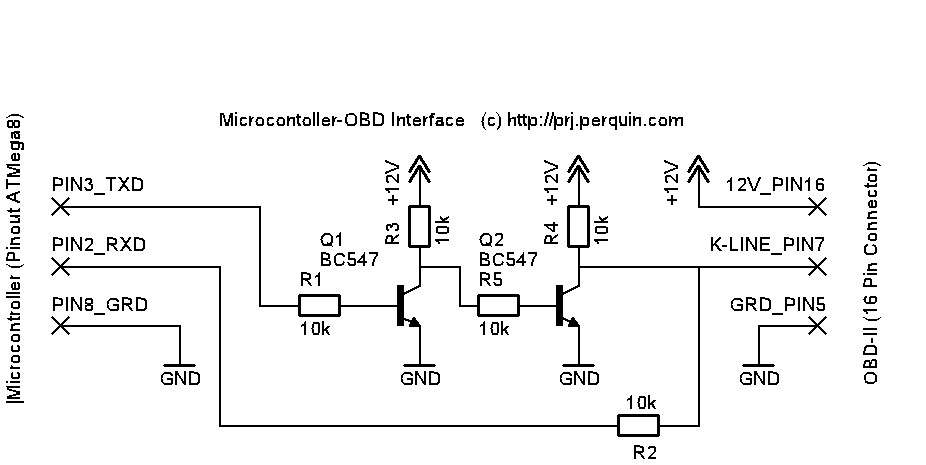 OBD2 K-line connection diagram
2. Understanding the Basics of OBD2 System
To effectively use an OBD2 diagnostic chart, you must understand the fundamental components and functions of the OBD2 system. This knowledge ensures that you can accurately interpret the diagnostic chart and apply it to real-world troubleshooting.
2.1. Overview of OBD2 System
The OBD2 system monitors a vehicle’s critical systems, including the engine, transmission, and emissions control systems. According to the Environmental Protection Agency (EPA), OBD2 systems have been mandatory on all cars sold in the U.S. since 1996 to ensure emissions compliance. The key functions of the OBD2 system are:
- Monitoring Sensors: Continuously checking the performance of various sensors.
- Diagnostic Trouble Codes (DTCs): Generating codes when a problem is detected.
- Reporting: Providing data to mechanics and vehicle owners via scan tools.
2.2. Essential Components of OBD2 System
The essential components of the OBD2 system include:
- ECU: The central processing unit that controls and monitors the vehicle’s systems.
- Sensors: Devices like oxygen sensors, mass airflow sensors, and coolant temperature sensors.
- Actuators: Components that perform actions based on ECU commands, such as fuel injectors and ignition coils.
- DLC: The 16-pin connector where scan tools are connected.
2.3. How Data Flows Within the OBD2 System
Data flow within the OBD2 system occurs as follows:
- Sensor Input: Sensors collect data and send signals to the ECU.
- ECU Processing: The ECU analyzes the sensor data and compares it against pre-programmed parameters.
- Fault Detection: If the ECU detects a discrepancy, it generates a DTC.
- Data Storage: The DTC is stored in the ECU’s memory.
- Reporting: A scan tool retrieves the DTC from the ECU via the DLC.
3. How to Read an OBD2 Schematic
Reading an OBD2 diagnostic chart involves understanding the symbols, lines, and labels that represent the various components and connections. This section provides a step-by-step guide to help you navigate and interpret these complex diagrams.
3.1. Common Symbols and Abbreviations
An OBD II wiring diagram uses standard symbols to represent electrical components. Understanding these symbols is crucial for interpreting the diagnostic chart. Some common symbols and abbreviations include:
- Resistor: Represented by a zigzag line.
- Capacitor: Represented by two parallel lines.
- Diode: Represented by a triangle pointing to a line.
- Ground: Represented by a series of horizontal lines decreasing in size.
- ECU: Engine Control Unit.
- DLC: Diagnostic Link Connector.
- GND: Ground.
- VCC: Voltage Common Collector (power supply).
3.2. Tracing Electrical Circuits
To trace electrical circuits in an OBD II wiring diagram:
- Start at the Power Source: Identify the voltage source (e.g., battery) and trace the circuit from there.
- Follow the Lines: Follow the lines representing wires to see where the electrical current flows.
- Identify Components: Note each component the circuit passes through, such as sensors, relays, and fuses.
- Look for Ground Connections: Ensure the circuit has a complete path back to the ground.
3.3. Interpreting Wiring Diagrams
Interpreting wiring diagrams involves understanding how components are connected and how signals are transmitted. According to Bosch Automotive Handbook, accurate interpretation of wiring diagrams is essential for diagnosing electrical faults. Follow these steps:
- Identify the System: Determine which system the diagnostic chart represents (e.g., fuel injection, ignition).
- Locate Key Components: Find the key components in the system, such as the ECU and relevant sensors.
- Analyze Connections: Examine how these components are connected, noting the wire colors and connector numbers.
- Understand Signal Flow: Trace the flow of signals to understand how the system operates under normal conditions.
4. Essential Tools for Working with OBD2 Schematics
Having the right tools is essential for effectively working with OBD2 diagnostic charts. This section outlines the necessary tools for diagnosing and repairing vehicle systems using OBD II wiring diagrams.
4.1. Multimeters
A multimeter is an essential tool for measuring voltage, current, and resistance in electrical circuits. According to Fluke Corporation, a reliable multimeter is crucial for accurate diagnostics. Key features to look for in a multimeter include:
- Auto-Ranging: Automatically selects the appropriate measurement range.
- Continuity Testing: Checks if a circuit is complete.
- Accuracy: Ensures precise measurements.
4.2. Scan Tools
Scan tools are used to read Diagnostic Trouble Codes (DTCs) from the vehicle’s ECU. According to a study by the National Institute for Automotive Service Excellence (ASE), using a scan tool can significantly reduce diagnostic time. Types of scan tools include:
- Basic OBD2 Scanners: Read and clear DTCs.
- Advanced Scan Tools: Provide live data, component testing, and bi-directional controls.
4.3. Wiring Test Kits
Wiring test kits help diagnose faults in wiring harnesses. These kits typically include:
- Test Leads: For connecting to various points in the circuit.
- Back Probes: For testing connectors without damaging them.
- Insulation Piercing Probes: For testing wires without removing insulation.
 Automotive wiring diagram using PIC controller
5. Common OBD2 Diagnostic Scenarios
Understanding common OBD2 diagnostic scenarios can help you apply your knowledge of OBD II wiring diagrams to real-world problems. This section outlines several typical diagnostic situations and how to approach them.
5.1. Identifying Open Circuits
An open circuit occurs when the electrical path is broken, preventing current flow. To identify an open circuit:
- Use a Multimeter: Set the multimeter to continuity mode and check the circuit.
- Check Wiring: Inspect wires for breaks, corrosion, or damage.
- Test Connectors: Ensure connectors are properly seated and free from corrosion.
5.2. Diagnosing Short Circuits
A short circuit occurs when electricity flows along an unintended path, often to ground. To diagnose a short circuit:
- Check Fuses: Look for blown fuses, which indicate excessive current flow.
- Inspect Wiring: Examine wires for damaged insulation that could cause a short to ground.
- Use a Multimeter: Measure resistance between the circuit and ground to identify shorts.
5.3. Troubleshooting Sensor Failures
Sensor failures can cause a variety of issues, from poor engine performance to emissions problems. To troubleshoot sensor failures:
- Read DTCs: Use a scan tool to retrieve DTCs related to the sensor.
- Check Sensor Wiring: Inspect the sensor’s wiring and connections.
- Test Sensor Output: Use a multimeter to measure the sensor’s output voltage or resistance and compare it to specifications.
6. Step-by-Step Guide to Diagnosing a Fault Using OBD2 Schematic
This section provides a detailed, step-by-step guide to diagnosing a fault using an OBD II diagnostic chart, ensuring you can systematically troubleshoot vehicle issues.
6.1. Step 1: Retrieve Diagnostic Trouble Codes (DTCs)
- Connect Scan Tool: Plug the scan tool into the DLC.
- Power On: Turn the ignition to the “on” position without starting the engine.
- Read Codes: Use the scan tool to read and record any DTCs.
6.2. Step 2: Consult the OBD2 Schematic
- Identify Relevant System: Determine which system the DTC relates to (e.g., fuel system, ignition system).
- Locate Components: Find the components associated with the DTC on the OBD II wiring diagram.
- Trace the Circuit: Follow the electrical paths between these components.
6.3. Step 3: Perform Circuit Testing
- Inspect Wiring: Check the wiring for damage, corrosion, or loose connections.
- Test Continuity: Use a multimeter to test the continuity of the circuit.
- Measure Voltage and Resistance: Measure voltage and resistance at various points in the circuit to identify faults.
6.4. Step 4: Verify the Repair
- Clear DTCs: After making repairs, clear the DTCs using the scan tool.
- Test Drive: Take the vehicle for a test drive to ensure the problem is resolved.
- Recheck Codes: Recheck for DTCs to confirm that the repair was successful.
7. Advanced Techniques for OBD2 Diagnostics
For more complex diagnostic issues, advanced techniques may be necessary. This section covers some of these techniques, providing you with the knowledge to tackle challenging problems.
7.1. Using Oscilloscopes
An oscilloscope displays electrical signals as waveforms, allowing you to analyze signal quality and identify intermittent faults. According to Tektronix, an oscilloscope is invaluable for diagnosing complex electrical issues. Key uses of an oscilloscope include:
- Signal Analysis: Examining the shape and amplitude of electrical signals.
- Intermittent Fault Detection: Identifying problems that occur sporadically.
- Component Testing: Evaluating the performance of sensors and actuators.
7.2. Performing Voltage Drop Tests
A voltage drop test measures the voltage drop across a circuit, which can indicate resistance due to corrosion or poor connections. According to the Automotive Electronics Council (AEC), voltage drop testing is an effective method for identifying wiring issues. To perform a voltage drop test:
- Connect Multimeter: Connect the multimeter across the circuit you want to test.
- Apply Load: Apply a load to the circuit (e.g., turn on a light).
- Measure Voltage Drop: Measure the voltage drop across the circuit; excessive voltage drop indicates a problem.
7.3. Utilizing OEM Diagnostic Software
Original Equipment Manufacturer (OEM) diagnostic software provides advanced diagnostic capabilities specific to the vehicle’s make and model. According to a study by the National Automotive Service Task Force (NASTF), using OEM software can significantly improve diagnostic accuracy. Key features of OEM software include:
- Advanced Diagnostics: Access to detailed diagnostic information.
- Programming: Ability to reprogram ECUs.
- Component Calibration: Calibration of sensors and actuators.
 Schematic diagram of Arduino UNO connected to OBD2 K-line
8. OBD2 Compliance and Standards
Understanding OBD2 compliance and standards is essential for ensuring that diagnostic procedures are accurate and effective. This section outlines the key standards and requirements for OBD2 systems.
8.1. Overview of OBD2 Standards
OBD2 standards are mandated by regulatory bodies to ensure that vehicles meet emissions requirements and provide standardized diagnostic information. According to the Society of Automotive Engineers (SAE), OBD2 standards include:
- SAE J1979: Defines diagnostic test modes.
- SAE J1850: Specifies communication protocols.
- ISO 15765: Defines Controller Area Network (CAN) communication.
8.2. Regulatory Requirements for OBD2
Regulatory requirements for OBD2 are enforced by agencies like the Environmental Protection Agency (EPA) in the United States and the European Union. These requirements mandate:
- Emissions Monitoring: Monitoring of emissions-related components.
- Standardized DTCs: Use of standardized Diagnostic Trouble Codes.
- Data Accessibility: Providing access to diagnostic data via the DLC.
8.3. Ensuring Compliance in Diagnostics
To ensure compliance in diagnostics:
- Use Compliant Tools: Use scan tools and diagnostic software that meet OBD2 standards.
- Follow Standard Procedures: Adhere to standardized diagnostic procedures.
- Stay Updated: Stay informed about changes to OBD2 standards and regulatory requirements.
9. Benefits of Using OBD2 Schematics
Using OBD2 diagnostic charts offers numerous benefits for automotive technicians and vehicle owners. This section highlights these advantages, emphasizing the value of understanding and utilizing these diagnostic charts.
9.1. Improved Diagnostic Accuracy
OBD II wiring diagrams provide detailed information about the vehicle’s electrical system, which helps improve diagnostic accuracy. By tracing circuits and testing components, technicians can pinpoint faults more effectively, reducing the risk of misdiagnosis. According to a study by Bosch, using diagnostic charts can reduce diagnostic errors by up to 30%.
9.2. Reduced Repair Time
By providing a clear roadmap of the vehicle’s electrical system, OBD2 diagnostic charts help reduce repair time. Technicians can quickly identify the location of faults and the steps needed to repair them. According to the National Institute for Automotive Service Excellence (ASE), using diagnostic charts can reduce repair time by up to 20%.
9.3. Enhanced Troubleshooting Capabilities
OBD II wiring diagrams enhance troubleshooting capabilities by providing a comprehensive view of the vehicle’s systems. Technicians can use these diagnostic charts to understand how different components interact and to identify the root cause of complex problems.
10. Common Mistakes to Avoid When Using OBD2 Schematics
Even with a good understanding of OBD2 diagnostic charts, it’s easy to make mistakes. This section outlines common errors to avoid, ensuring you use these diagnostic charts effectively.
10.1. Misinterpreting Symbols
Misinterpreting symbols on an OBD II wiring diagram can lead to incorrect diagnoses and repairs. Always refer to a reliable reference guide to ensure you understand the meaning of each symbol.
10.2. Ignoring Wiring Colors
Wiring colors are used to identify different circuits and signal paths. Ignoring wiring colors can lead to connecting components incorrectly, causing further damage. Always pay attention to wiring colors and match them when making connections.
10.3. Neglecting Ground Connections
Ground connections are essential for completing electrical circuits. Neglecting ground connections can cause components to malfunction or fail altogether. Always ensure that ground connections are clean and secure.
11. OBD2 Schematic Resources
Access to reliable resources is essential for effectively using OBD2 diagnostic charts. This section provides a list of resources that can help you find diagnostic charts and learn more about OBD2 systems.
11.1. Online Databases
Several online databases provide access to OBD II wiring diagrams and technical information. Some popular databases include:
- ALLDATA: Offers comprehensive diagnostic charts and repair information.
- Mitchell 1: Provides detailed diagnostic charts and troubleshooting guides.
- Identifix: Offers a database of diagnostic information and repair procedures.
11.2. Manufacturer Websites
Manufacturer websites often provide access to diagnostic charts and technical documentation for their vehicles. Check the manufacturer’s website for your specific vehicle model to find the most accurate and up-to-date information.
11.3. Automotive Forums and Communities
Automotive forums and online communities can be valuable resources for finding diagnostic charts and getting advice from experienced technicians. Some popular forums include:
- Automotive Forums: A general forum for automotive enthusiasts and technicians.
- iATN (International Automotive Technicians Network): A professional network for automotive technicians.
- OBD2-SCANNER.EDU.VN: Offers expert advice and resources on OBD2 diagnostics and repair.
12. Future Trends in OBD2 Technology
OBD2 technology continues to evolve, with new features and capabilities being introduced. This section explores some of the future trends in OBD2 technology, helping you stay ahead of the curve.
12.1. Enhanced Diagnostic Capabilities
Future OBD2 systems will offer enhanced diagnostic capabilities, including:
- Predictive Diagnostics: Using data analytics to predict potential failures.
- Remote Diagnostics: Allowing technicians to diagnose vehicles remotely.
- Advanced Sensor Monitoring: Monitoring a wider range of vehicle parameters.
12.2. Integration with Telematics Systems
OBD2 systems are increasingly being integrated with telematics systems, which provide real-time data on vehicle performance and location. This integration enables:
- Remote Vehicle Monitoring: Tracking vehicle performance and identifying potential issues.
- Fleet Management: Managing vehicle fleets more efficiently.
- Usage-Based Insurance: Providing insurance rates based on driving behavior.
12.3. Cybersecurity Enhancements
As vehicles become more connected, cybersecurity is becoming increasingly important. Future OBD2 systems will incorporate enhanced cybersecurity measures to protect against hacking and data breaches. These measures include:
- Secure Communication Protocols: Using encrypted communication protocols to protect data.
- Intrusion Detection Systems: Detecting and preventing unauthorized access to vehicle systems.
- Software Updates: Regularly updating software to address security vulnerabilities.
13. Case Studies: Successful Diagnoses with OBD2 Schematics
Real-world examples can illustrate the power and utility of OBD II wiring diagrams. This section presents case studies of successful diagnoses using OBD2 diagnostic charts.
13.1. Case Study 1: Diagnosing a Misfire
A vehicle was experiencing a misfire, and the technician retrieved a DTC indicating a problem with the ignition coil. By consulting the OBD2 diagnostic chart, the technician was able to trace the wiring from the ECU to the ignition coil and identify a broken wire. After repairing the wire, the misfire was resolved.
13.2. Case Study 2: Troubleshooting an ABS Fault
A vehicle had an ABS fault, and the technician retrieved a DTC indicating a problem with the wheel speed sensor. By consulting the OBD2 diagnostic chart, the technician was able to trace the wiring from the ABS control module to the wheel speed sensor and identify a corroded connector. After cleaning the connector, the ABS fault was resolved.
13.3. Case Study 3: Resolving an Emissions Issue
A vehicle failed an emissions test, and the technician retrieved a DTC indicating a problem with the oxygen sensor. By consulting the OBD2 diagnostic chart, the technician was able to trace the wiring from the ECU to the oxygen sensor and identify a short circuit. After repairing the wiring, the emissions issue was resolved.
14. FAQ About OBD2 Schematics
This section addresses frequently asked questions about OBD2 diagnostic charts, providing quick answers to common queries.
14.1. What is an OBD2 Scanner?
An OBD2 scanner is a diagnostic tool used to retrieve Diagnostic Trouble Codes (DTCs) from a vehicle’s Engine Control Unit (ECU). These codes help identify potential issues with the vehicle’s engine, transmission, and other systems.
14.2. How Do I Read OBD2 Codes?
To read OBD2 codes, plug the scanner into the Diagnostic Link Connector (DLC), turn on the ignition, and follow the scanner’s prompts to retrieve the codes. The scanner will display a series of codes, each corresponding to a specific problem.
14.3. What Are Common OBD2 Codes and Their Meanings?
Common OBD2 codes include:
- P0300: Random/Multiple Cylinder Misfire Detected.
- P0171: System Too Lean (Bank 1).
- P0420: Catalyst System Efficiency Below Threshold (Bank 1).
- P0101: Mass Air Flow (MAF) Sensor Circuit Range/Performance.
- P0301: Cylinder 1 Misfire Detected.
14.4. Can I Fix OBD2 Errors Myself?
Whether you can fix OBD2 errors yourself depends on the complexity of the issue. Simple problems like a loose gas cap can be easily fixed, while more complex issues may require professional assistance.
14.5. How Often Should I Run an OBD2 Scan?
You should run an OBD2 scan whenever you notice symptoms like the check engine light turning on, poor engine performance, or decreased fuel efficiency. Regular scans can help identify and address problems early.
14.6. Where Can I Find an OBD2 Schematic for My Car?
You can find an OBD II wiring diagram for your car in online databases like ALLDATA and Mitchell 1, manufacturer websites, and automotive forums.
14.7. Are All OBD2 Schematics the Same?
No, OBD2 diagnostic charts vary depending on the vehicle’s make, model, and year. Always use a diagnostic chart specific to your vehicle.
14.8. What Does DLC Stand For?
DLC stands for Diagnostic Link Connector, the 16-pin connector used to access the vehicle’s OBD2 system.
14.9. What is the Engine Control Unit (ECU)?
The Engine Control Unit (ECU) is the computer that manages the engine’s functions and reports diagnostic data. It monitors sensors, controls actuators, and stores Diagnostic Trouble Codes (DTCs).
14.10. How Do I Clear OBD2 Codes?
To clear OBD2 codes, use a scan tool to connect to the vehicle’s ECU and select the option to clear codes. Keep in mind that clearing codes without addressing the underlying problem may cause the check engine light to reappear.
15. Conclusion
Understanding and using an OBD2 diagnostic chart is crucial for effective vehicle diagnostics and repair. At OBD2-SCANNER.EDU.VN, we provide the resources and expertise you need to master OBD2 diagnostics. From understanding the basics of OBD2 systems to advanced diagnostic techniques, our goal is to empower you with the knowledge and tools to keep your vehicle running smoothly. Whether you’re a seasoned technician or a vehicle owner, our comprehensive resources can help you navigate the complexities of OBD2 diagnostics. Remember, accurate diagnostics lead to effective repairs, saving you time and money.
Ready to take your automotive diagnostics to the next level? Contact us today at 123 Main Street, Los Angeles, CA 90001, United States, via Whatsapp at +1 (641) 206-8880, or visit our website at OBD2-SCANNER.EDU.VN for expert advice and services. Let OBD2-SCANNER.EDU.VN be your trusted partner in automotive diagnostics and repair.