Unlock the secrets of your vehicle’s inner workings with Stm32 Obd2 integration. OBD2-SCANNER.EDU.VN offers comprehensive insights and solutions for automotive diagnostics, empowering you to understand and address your vehicle’s needs effectively.
Contents
- 1. What is STM32 OBD2 and Why is it Important?
- 2. Key Components for STM32 OBD2 Implementation
- 3. Understanding OBD2 Protocols and Standards
- 4. Setting Up the STM32 Development Environment for OBD2
- 5. Initializing CAN Communication on STM32
- 6. Reading CAN Messages with STM32
- 7. Decoding OBD2 Data and Trouble Codes
- 8. Common Challenges and Solutions in STM32 OBD2 Development
- 9. Advanced STM32 OBD2 Applications
- 10. OBD2-SCANNER.EDU.VN: Your Partner in STM32 OBD2 Development
- 11. Frequently Asked Questions (FAQ) About STM32 OBD2
- 12. Real-World Examples of STM32 OBD2 Projects
- 13. The Future of STM32 OBD2 Technology
- 14. Connect with OBD2-SCANNER.EDU.VN for Expert Guidance
1. What is STM32 OBD2 and Why is it Important?
STM32 OBD2 refers to the integration of the STM32 microcontroller family with the On-Board Diagnostics II (OBD2) system in vehicles. This combination empowers users to access and interpret a wealth of diagnostic information from their vehicles. According to the Environmental Protection Agency (EPA), all cars and light trucks manufactured after 1996 are legally required to support OBD2, creating a standardized interface for accessing vehicle data.
- Enhanced Diagnostics: STM32 microcontrollers can be programmed to communicate with a vehicle’s OBD2 port, retrieve diagnostic trouble codes (DTCs), sensor data, and other crucial information. This allows for real-time monitoring of vehicle performance, identification of potential issues, and proactive maintenance.
- Customizable Solutions: Unlike generic OBD2 scanners, STM32-based solutions offer a high degree of customization. Developers can tailor the functionality to specific needs, such as creating custom dashboards, implementing advanced diagnostic algorithms, or integrating with other systems.
- Cost-Effectiveness: STM32 microcontrollers are relatively inexpensive, making them an attractive option for developing affordable OBD2 solutions. This is particularly beneficial for DIY enthusiasts and small automotive repair shops.
- Educational Opportunities: Working with STM32 OBD2 provides valuable hands-on experience in embedded systems development, automotive diagnostics, and data analysis. It’s an excellent platform for learning about vehicle technology and gaining practical skills.
STM32 OBD2 integration opens up a world of possibilities for automotive enthusiasts, developers, and repair professionals. By leveraging the power of STM32 microcontrollers, users can gain deeper insights into their vehicles, troubleshoot issues more effectively, and create innovative solutions for the automotive industry.
2. Key Components for STM32 OBD2 Implementation
Implementing STM32 OBD2 requires several key components working together seamlessly. Let’s explore these components in detail:
- STM32 Microcontroller: The heart of the system, the STM32 microcontroller, handles communication with the OBD2 port, data processing, and user interface. According to STMicroelectronics, the STM32 family offers a wide range of options with varying processing power, memory, and peripherals to suit different OBD2 applications.
- OBD2 Connector: This physical interface connects the STM32 microcontroller to the vehicle’s OBD2 port. Standard OBD2 connectors are readily available and provide access to essential communication protocols like CAN, K-Line, and J1850.
- CAN Transceiver (MCP2551): The CAN transceiver acts as a bridge between the STM32 microcontroller and the vehicle’s CAN bus. It converts the digital signals from the microcontroller into differential signals suitable for transmission over the CAN bus and vice versa. Microchip’s MCP2551 is a popular choice for its robust performance and compatibility.
- Level Shifter (if needed): Some OBD2 implementations may require level shifters to ensure proper voltage compatibility between the STM32 microcontroller and the vehicle’s communication bus.
- Power Supply: A stable power supply is crucial for reliable operation. This can be a simple voltage regulator or a more sophisticated power management system, depending on the application’s requirements.
- UART Interface: This interface is used for sending messages from device, such as “NO MESSAGE!” or “A NEW MESSAGE ARRIVED!”.
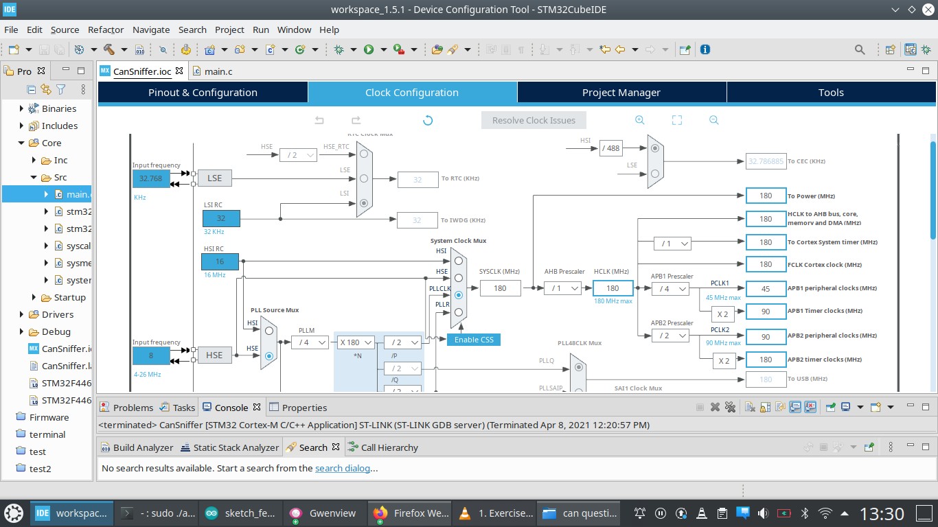 STM32 Microcontroller for OBD2 Applications
Alt Text: STM32 microcontroller clock tree configuration showing APB1 clock rate at 45 MHz, crucial for calculating the correct CAN bus baud rate in OBD2 applications.
By carefully selecting and integrating these components, developers can create robust and reliable STM32 OBD2 systems that provide valuable insights into vehicle performance and diagnostics.
3. Understanding OBD2 Protocols and Standards
OBD2 communication relies on several protocols and standards, each with its own characteristics and applications. Grasping these protocols is vital for successful STM32 OBD2 integration. Let’s delve into some of the key ones:
- CAN (Controller Area Network): CAN is the most prevalent protocol in modern vehicles, offering high-speed communication and robust error handling. According to the Society of Automotive Engineers (SAE), CAN is used for transmitting a wide range of data, including engine parameters, sensor readings, and diagnostic information.
- ISO 9141-2 (K-Line): This older protocol is still found in some vehicles and uses a single wire for communication. It’s slower than CAN but simpler to implement.
- SAE J1850 VPW and PWM: These protocols were commonly used in older American vehicles. VPW (Variable Pulse Width) and PWM (Pulse Width Modulation) differ in their signaling methods but serve similar purposes.
- ISO 15765-4 (Diagnostic on CAN): This standard defines how diagnostic messages are transmitted over the CAN bus. It specifies the message format, addressing scheme, and communication procedures.
When working with STM32 OBD2, it’s important to identify the specific protocol used by the target vehicle. This information is typically available in the vehicle’s service manual or online databases. Once the protocol is known, the STM32 microcontroller can be programmed to communicate accordingly.
4. Setting Up the STM32 Development Environment for OBD2
Before diving into STM32 OBD2 development, you’ll need to set up a suitable development environment. This involves installing the necessary software tools and configuring your hardware. Let’s explore the steps involved:
- Install STM32CubeIDE: STM32CubeIDE is a comprehensive integrated development environment (IDE) provided by STMicroelectronics. It includes a code editor, compiler, debugger, and other essential tools for STM32 development. Download the latest version from the STMicroelectronics website and follow the installation instructions.
- Install a Serial Communication Program: A serial communication program, such as PuTTY or Tera Term, will be needed to view output on your computer when using UART2 to send a message.
- Install the STM32Cube HAL Library: The STM32Cube Hardware Abstraction Layer (HAL) library provides a set of functions that simplify access to the STM32 microcontroller’s peripherals. STM32CubeIDE typically includes the HAL library for various STM32 series.
- Configure Your STM32 Board: Connect your STM32 board to your computer using a USB cable. Install the necessary drivers if prompted. In STM32CubeIDE, create a new project for your STM32 board and configure the project settings according to your hardware setup.
- Set up the CAN Interface: Configure the CAN interface on your STM32 microcontroller using the STM32CubeIDE’s peripheral configuration tools. Specify the CAN bus speed, filter settings, and other relevant parameters.
With your development environment set up, you’re ready to start writing code for your STM32 OBD2 application.
5. Initializing CAN Communication on STM32
Initializing CAN communication on the STM32 involves configuring the CAN peripheral and setting up filters to receive relevant messages. Here’s a step-by-step guide:
- Enable the CAN Peripheral: In your STM32 project, enable the CAN peripheral using the STM32CubeIDE’s peripheral configuration tools or by manually setting the appropriate registers.
- Configure the CAN Baud Rate: The CAN baud rate determines the communication speed on the CAN bus. Common baud rates for OBD2 applications are 500 kbps and 250 kbps. Set the CAN baud rate in your STM32 project according to the vehicle’s specifications.
- Configure CAN Filters: CAN filters allow the STM32 microcontroller to selectively receive messages based on their identifier (ID). Setting up filters is crucial for reducing the amount of data that the microcontroller needs to process. In the provided code, all filter bits are set to 0, which should theoretically allow the reception of all CAN messages.
- Initialize the CAN Peripheral: Call the
HAL_CAN_Init()function to initialize the CAN peripheral with the configured settings. - Start the CAN Peripheral: Call the
HAL_CAN_Start()function to start the CAN peripheral and enable message reception.
static void MX_CAN1_Init(void) {
  hcan1.Instance = CAN1;
  hcan1.Init.Prescaler = 5;
  hcan1.Init.Mode = CAN_MODE_NORMAL;
  hcan1.Init.SyncJumpWidth = CAN_SJW_1TQ;
  hcan1.Init.TimeSeg1 = CAN_BS1_15TQ;
  hcan1.Init.TimeSeg2 = CAN_BS2_2TQ;
  hcan1.Init.TimeTriggeredMode = DISABLE;
  hcan1.Init.AutoBusOff = DISABLE;
  hcan1.Init.AutoWakeUp = DISABLE;
  hcan1.Init.AutoRetransmission = DISABLE;
  hcan1.Init.ReceiveFifoLocked = DISABLE;
  hcan1.Init.TransmitFifoPriority = DISABLE;
  if (HAL_CAN_Init(&hcan1) != HAL_OK) {
    Error_Handler();
  }
}
This code snippet demonstrates how to initialize the CAN1 peripheral on an STM32 microcontroller. It configures the prescaler, operating mode, timing segments, and other parameters. The HAL_CAN_Init() function performs the actual initialization, and any errors are handled by the Error_Handler() function.
6. Reading CAN Messages with STM32
Once the CAN peripheral is initialized, you can start reading CAN messages received from the vehicle. Here’s how to do it:
- Implement a CAN Receive Interrupt Handler: Configure the CAN peripheral to generate an interrupt when a new message is received. Implement an interrupt handler function that will be called when this interrupt occurs.
- Read the CAN Message: Inside the interrupt handler, use the
HAL_CAN_GetRxMessage()function to read the received CAN message from the CAN receive FIFO. This function retrieves the message identifier, data length, and data bytes. - Process the CAN Message: After reading the CAN message, you can process the data according to your application’s requirements. This may involve decoding the data, displaying it on a screen, or transmitting it to another system.
void CAN1_Rx(void) {
  uint8_t CAN_Rx_Msg[5];
  CAN_RxHeaderTypeDef CAN1_RxHeader;
  while(1) {
    if(! HAL_CAN_GetRxFifoFillLevel(&hcan1, CAN_RX_FIFO0)) {
      HAL_UART_Transmit(&huart2, (unsigned char *)"NO MESSAGE!n", strlen("NO MESSAGE!n"), HAL_MAX_DELAY);
      HAL_Delay(1500);
    } else {
      HAL_UART_Transmit(&huart2, (unsigned char *)"MESSAGE ARRIVED!n", strlen("MESSAGE ARRIVED!n"), HAL_MAX_DELAY);
      HAL_CAN_GetRxMessage(&hcan1, CAN_RX_FIFO0, &CAN1_RxHeader, CAN_Rx_Msg);
      HAL_UART_Transmit(&huart2, (unsigned char *)CAN_Rx_Msg, sizeof(CAN_Rx_Msg), HAL_MAX_DELAY);
    }
  }
}
This code snippet shows how to receive CAN messages using the HAL_CAN_GetRxMessage() function. It continuously checks the receive FIFO for new messages. If a message is available, it reads the message header and data and then transmits the data over UART2. If no message is available, it transmits “NO MESSAGE!” over UART2.
7. Decoding OBD2 Data and Trouble Codes
OBD2 data is transmitted in a standardized format, but decoding it requires understanding the specific parameters and trouble codes. Here’s an overview of the process:
- Understand PIDs (Parameter IDs): PIDs are codes that identify specific data parameters, such as engine speed, coolant temperature, and fuel pressure. The SAE J1979 standard defines a set of standard PIDs that all OBD2-compliant vehicles must support.
- Consult OBD2 Documentation: Refer to OBD2 documentation, such as the SAE J1979 standard or online databases, to determine the meaning and scaling of each PID.
- Decode the Data: Use the information from the OBD2 documentation to decode the raw data received from the vehicle. This may involve applying scaling factors, converting units, or performing other calculations.
- Interpret DTCs (Diagnostic Trouble Codes): DTCs are codes that indicate specific faults or malfunctions in the vehicle’s systems. The SAE J2012 standard defines a set of standard DTCs that all OBD2-compliant vehicles must support.
- Look Up DTCs: Use an OBD2 code reader or online database to look up the meaning of each DTC. This will provide information about the potential cause of the fault and the recommended repair procedures.
Decoding OBD2 data and trouble codes can be complex, but it’s essential for understanding the information provided by the vehicle. With the right documentation and tools, you can effectively interpret OBD2 data and diagnose vehicle problems.
8. Common Challenges and Solutions in STM32 OBD2 Development
STM32 OBD2 development can present several challenges. Here are some common issues and potential solutions:
- No CAN Messages Received: If you’re not receiving any CAN messages, check the following:
- CAN Bus Connection: Ensure that the STM32 microcontroller is properly connected to the vehicle’s OBD2 port and that the CAN transceiver is correctly wired.
- CAN Baud Rate: Verify that the CAN baud rate configured in your STM32 project matches the vehicle’s CAN bus speed.
- CAN Filters: Double-check your CAN filter settings to ensure that you’re not accidentally filtering out the messages you want to receive.
- Termination Resistor: Ensure that a 120-ohm termination resistor is present at each end of the CAN bus, especially if your device is a terminal node.
- Incorrect Data Decoding: If you’re receiving data but it’s not being decoded correctly, check the following:
- PID Documentation: Verify that you’re using the correct PID documentation for your vehicle and that you understand the scaling and units for each parameter.
- Data Alignment: Ensure that you’re correctly aligning the data bytes in the CAN message when decoding multi-byte parameters.
- Endianness: Be aware of the endianness (byte order) of the data and adjust your decoding accordingly.
- Communication Errors: CAN communication can be susceptible to errors due to noise or other interference. Implement error handling mechanisms in your code to detect and handle communication errors gracefully.
By addressing these common challenges and implementing appropriate solutions, you can improve the reliability and accuracy of your STM32 OBD2 system.
9. Advanced STM32 OBD2 Applications
Beyond basic data acquisition and trouble code reading, STM32 OBD2 can be used for a wide range of advanced applications:
- Custom Dashboards: Create custom dashboards that display real-time vehicle data in a visually appealing and informative way.
- Data Logging: Log vehicle data over time for analysis and performance monitoring.
- Remote Diagnostics: Implement remote diagnostic capabilities that allow you to monitor vehicle health from a distance.
- Predictive Maintenance: Use machine learning algorithms to analyze vehicle data and predict potential maintenance needs.
- Performance Tuning: Adjust vehicle parameters, such as fuel injection and ignition timing, to optimize performance.
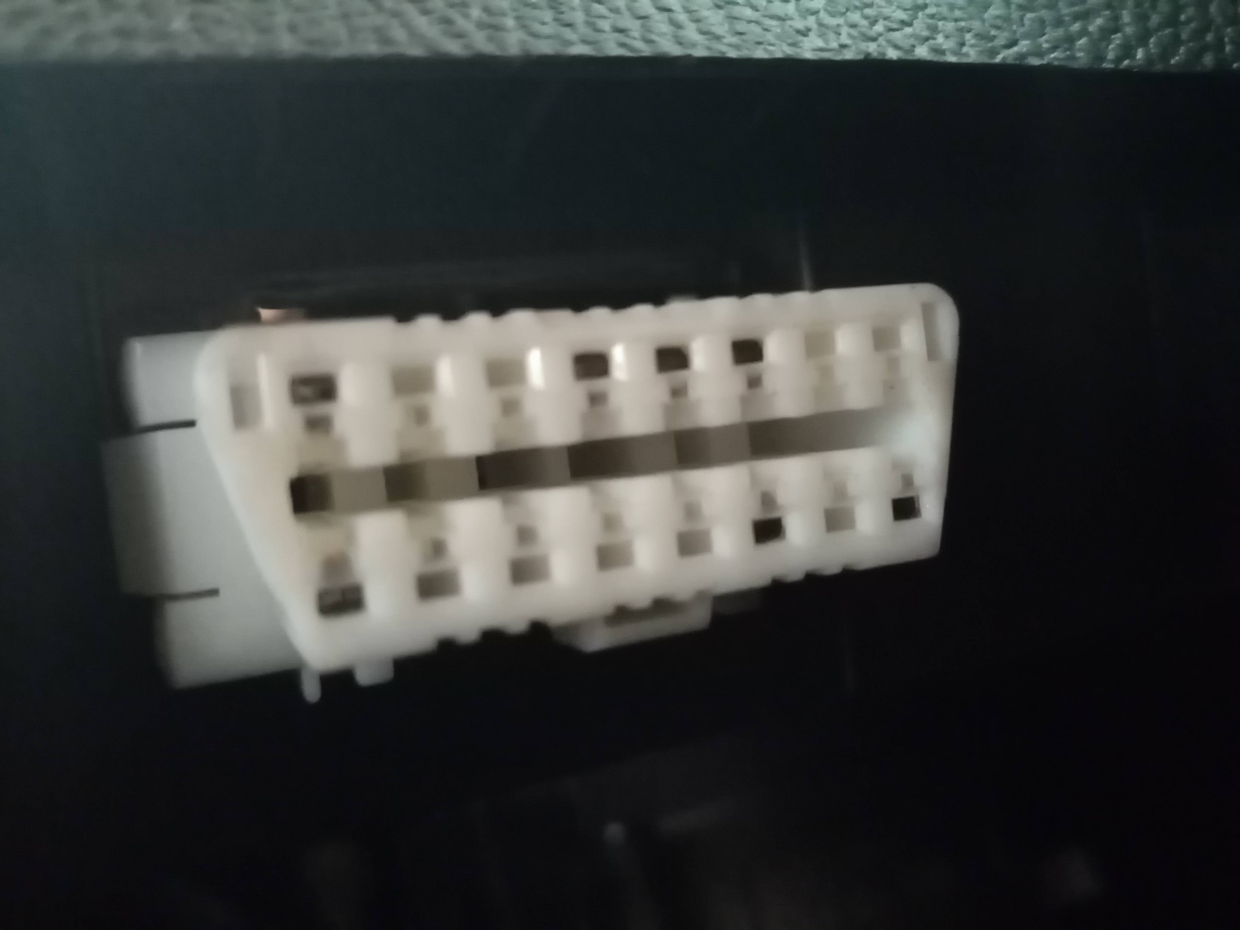 OBD2 Port Connections
Alt Text: Front view of an OBD2 port showing wired connections to pins, indicating CAN support on pins 6 and 14, and an unknown protocol on pins 1 and 9.
These advanced applications demonstrate the versatility and potential of STM32 OBD2. By leveraging the power of embedded systems and data analysis, you can create innovative solutions that enhance vehicle performance, safety, and efficiency.
10. OBD2-SCANNER.EDU.VN: Your Partner in STM32 OBD2 Development
At OBD2-SCANNER.EDU.VN, we’re passionate about empowering individuals and businesses with the knowledge and tools they need to succeed in STM32 OBD2 development. We offer a range of resources and services to support your projects:
- Comprehensive Tutorials: Our website features a wealth of tutorials and articles covering various aspects of STM32 OBD2 development, from basic concepts to advanced techniques.
- Example Code and Projects: We provide example code and project templates to help you get started quickly and easily.
- Expert Support: Our team of experienced engineers is available to provide expert support and guidance on your STM32 OBD2 projects.
- Custom Solutions: We offer custom development services for businesses that need tailored STM32 OBD2 solutions.
Whether you’re a hobbyist, student, or professional, OBD2-SCANNER.EDU.VN is your trusted partner in STM32 OBD2 development.
11. Frequently Asked Questions (FAQ) About STM32 OBD2
Here are some frequently asked questions about STM32 OBD2:
- What is an OBD2 scanner?
An OBD2 scanner is a device used to read diagnostic information from a vehicle’s OBD2 port, including trouble codes, sensor data, and other parameters. - How do I read OBD2 fault codes?
You can read OBD2 fault codes using an OBD2 scanner or an STM32-based OBD2 system. The scanner will display the codes, which can then be looked up in a database to determine their meaning. - What are common car errors and how to fix them?
Common car errors include engine misfires, sensor failures, and exhaust system problems. The specific cause and solution will depend on the DTC and the vehicle’s symptoms. - What is the difference between OBD and OBD2?
OBD (On-Board Diagnostics) is a general term for vehicle diagnostic systems. OBD2 is the second generation of this technology and is standardized across all vehicles manufactured after 1996. - How to choose an OBD2 scanner?
When choosing an OBD2 scanner, consider factors such as compatibility with your vehicle, features, ease of use, and price. - What is the CAN bus in OBD2?
The CAN (Controller Area Network) bus is a communication protocol used in modern vehicles to transmit data between various electronic control units (ECUs), including the engine control unit (ECU), transmission control unit (TCU), and anti-lock braking system (ABS). - Can I damage my car using an OBD2 scanner?
No, using an OBD2 scanner will not damage your car if used correctly. However, be careful when making changes to vehicle parameters, as incorrect settings can cause problems. - What is a PID in OBD2?
PID stands for Parameter ID. PIDs are codes that identify specific data parameters, such as engine speed, coolant temperature, and fuel pressure. - What is a DTC in OBD2?
DTC stands for Diagnostic Trouble Code. DTCs are codes that indicate specific faults or malfunctions in the vehicle’s systems. - Are all OBD2 scanners compatible with all cars?
Most OBD2 scanners are compatible with all cars manufactured after 1996. However, some scanners may have limited functionality or compatibility with certain makes and models.
12. Real-World Examples of STM32 OBD2 Projects
Here are some inspiring examples of real-world STM32 OBD2 projects:
- DIY Carputer: An enthusiast built a custom car computer using an STM32 microcontroller and an OBD2 interface. The carputer displays real-time vehicle data, provides navigation, and plays music.
- Fleet Management System: A company developed a fleet management system using STM32 OBD2 to track vehicle location, monitor driver behavior, and optimize fuel consumption.
- Automotive Research Tool: A university research team used STM32 OBD2 to collect data for studying vehicle emissions and developing new emission control technologies.
These examples demonstrate the diverse applications of STM32 OBD2 and its potential to solve real-world problems in the automotive industry.
13. The Future of STM32 OBD2 Technology
STM32 OBD2 technology is constantly evolving, driven by advancements in embedded systems, automotive technology, and data analytics. Here are some trends to watch for:
- Wireless Connectivity: Wireless OBD2 adapters are becoming increasingly popular, allowing users to connect their smartphones or tablets to their vehicle’s OBD2 port wirelessly.
- Cloud Integration: Cloud-based OBD2 platforms are emerging, providing remote data storage, analysis, and diagnostics.
- Artificial Intelligence: AI-powered OBD2 systems are being developed to provide more accurate diagnostics, predict maintenance needs, and optimize vehicle performance.
- Cybersecurity: As vehicles become more connected, cybersecurity is becoming increasingly important. STM32 OBD2 systems need to be designed with robust security measures to prevent unauthorized access and tampering.
The future of STM32 OBD2 is bright, with exciting opportunities for innovation and development. By staying informed about the latest trends and technologies, you can position yourself at the forefront of this dynamic field.
14. Connect with OBD2-SCANNER.EDU.VN for Expert Guidance
Ready to take your STM32 OBD2 projects to the next level? Contact OBD2-SCANNER.EDU.VN today! Our team of experts can provide you with the guidance and support you need to succeed.
- Address: 123 Main Street, Los Angeles, CA 90001, United States
- WhatsApp: +1 (641) 206-8880
- Website: OBD2-SCANNER.EDU.VN
Let OBD2-SCANNER.EDU.VN be your partner in unlocking the power of STM32 OBD2!
By understanding the fundamentals of STM32 OBD2, addressing common challenges, and exploring advanced applications, you can harness the power of vehicle diagnostics and create innovative solutions for the automotive industry.